
- High-Performance Doors
-
- Applications
-
-
-
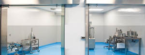
- Clean Room
Stainless steel or composite materials help maintain clean rooms.
-
-
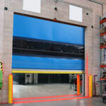
- Coolers
Quick opening speeds & tight seals for temperature control.
-
-
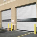
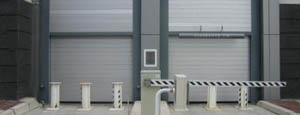
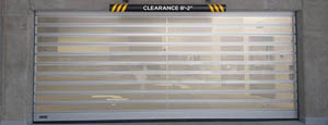
- Parking
Improve security & traffic flow and enhance architectural style.
-
-
- Hurricane Zone
Withstand winds up to 175 mph and comply with the Florida Building Code.
-
-
-
-
- USDA / FDA / cGMP
Increase productivity & address stringent USDA, FDA & cGMP requirements.
-
-
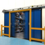
- Freezers
High-speed & perimeter seals minimize the air exchange between areas.
-
-
- Security
High speed & durability ensure secure access.
-
-
- Ventilation
Perforated or screen door panels allow improved air circulation.
-
-
-
-
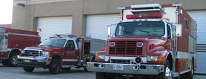
- Fire Station Emergency Response
When time is of the essence, high speed and reliability are crucial.
-
-
- Warehousing
Fast cycle times and secure seals keep environments separated.
-
-
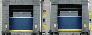
- Loading Dock
Rugged design & secure seal for oversized openings.
-
-
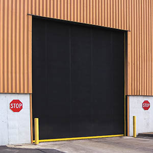
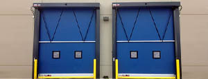
- Large Openings
Break-away functionality with rugged design seals oversized openings.
-
-
-
-
- Heavy Equipment
Withstands challenges of heavy equipment and fleet truck/car wash environments.
-
-
- Self-Storage
Fast opening speeds and reliable, durable construction keep facilities secure and protected.
-
-
- Industries
-
-
-
- Automotive Dealerships
Reduce energy costs, increase productivity and comfort and enhance customer perception.
-
-
- Cold Storage & Processing
Increase productivity and operational efficiency while reducing energy and maintenance costs.
-
-
- Parking
We offer solutions for Apartment / Condo & Loft, Standalone Parking Facilities and Office Buildings
-
-
-
-
- Food & Beverage
Doors specifically engineered for USDA/FDA and cGMP environments, and assured compliance for uncompromising performance.
-
-
- Mfg/Dist/Warehousing
A complete product line allows facilities to increase efficiency and safety and reduce maintenance and energy costs.
-
-
- Government
Ensure effective security and environmental controls are maintained for critical government operations.
-
-
-
-
- Transit
Keep operations running smoothly and efficient while reducing energy and maintenance costs.
-
-
- Pharma, Nutraceutical & Biotech
Doors that offer quick, secure access, environmental control and reliability for life science facilities.
-
-
- Support Resources
- Parts
- Contact Us
- Blog/News
- Why Rytec
- Sales Rep Locator
- Careers
- Dealers
- Architectural Resources












Why Choose RMU Switchgear for Global Power Distribution?
Global power distribution is becoming more demanding, not merely larger. The International Energy Agency’s Electricity 2024 report forecasts global electricity demand growth of about 3.4% annually through 2026. That growth places pressure on medium-voltage networks, especially in urban substations, renewable-energy projects, and industrial facilities.
Rmu Switchgear offers a compact way to manage these pressures. It combines switching, protection, and isolation inside a factory-tested enclosure. A typical unit can fit beside a transformer in a narrow concrete kiosk, reducing installation space and maintenance exposure. Its modular design also supports phased network expansion. Practical value matters.
Frédéric Godemel, Schneider Electric’s Executive Vice President for Power Systems and Services, has stated, “The energy transition is an electrification transition.” His observation explains why dependable medium-voltage equipment is becoming central to global infrastructure planning. The IEA’s Grid Investment report also highlights the need for faster investment in modern, flexible electricity networks.
However, Rmu Switchgear is not automatically the best choice. Engineers must verify fault ratings, climate conditions, remote-control requirements, service access, and local standards. IEC 62271-200 provides an important reference for metal-enclosed medium-voltage switchgear. Environmental performance also deserves closer attention, particularly where traditional SF6 insulation is used.
The better question is not whether Rmu Switchgear looks compact. It is whether the selected design remains safe, maintainable, and adaptable across decades of changing power demand. That answer depends on engineering evidence, supplier experience, and honest lifecycle evaluation.
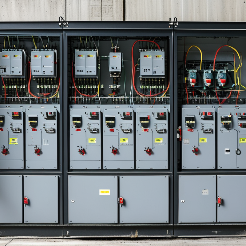
Table of Contents [Hide]
RMU Switchgear Defined: IEC 62271-200 Medium-Voltage Distribution
RMU Switchgear Defined: IEC 62271-200 Medium-Voltage Distribution
RMU switchgear is compact metal-enclosed equipment for medium-voltage networks. It controls, protects, and isolates distribution circuits in a small footprint. IEC 62271-200 applies to AC metal-enclosed switchgear above 1 kV and up to 52 kV. Common RMU assemblies include load-break switches, circuit breakers, earthing switches, and fuses. These functions support ring networks, where power can arrive from different directions. That improves supply continuity. Space remains limited.
In practical installations, technicians use visible position indicators and interlocking systems during switching operations. A sealed enclosure helps protect internal components from dust, moisture, and accidental contact. However, sealed does not mean maintenance-free. Cable terminations, pressure indicators, and operating mechanisms still need inspection. Internal arc classification also matters, especially in substations near buildings or public areas. Local installation conditions can change the correct specification.
For global power distribution, engineers should verify voltage, short-circuit withstand, insulation level, and environmental requirements. IEC 62271-200 compliance provides a reliable technical reference, but it does not replace site engineering. Cable interfaces must match local practices and available accessories. Protection settings should reflect transformer capacity and network fault levels. Field experience often reveals small problems early, such as unclear labels or restricted operating space. These details seem minor. They are not. Even a well-designed RMU can perform poorly when installation records, training, or maintenance access are overlooked.