
- High-Performance Doors
-
- Applications
-
-
-
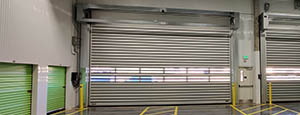
- Clean Room
Stainless steel or composite materials help maintain clean rooms.
-
-
- Coolers
Quick opening speeds & tight seals for temperature control.
-
-
- Parking
Improve security & traffic flow and enhance architectural style.
-
-
- Hurricane Zone
Withstand winds up to 175 mph and comply with the Florida Building Code.
-
-
-
-
- USDA / FDA / cGMP
Increase productivity & address stringent USDA, FDA & cGMP requirements.
-
-
- Freezers
High-speed & perimeter seals minimize the air exchange between areas.
-
-
- Security
High speed & durability ensure secure access.
-
-
- Ventilation
Perforated or screen door panels allow improved air circulation.
-
-
-
-
- Fire Station Emergency Response
When time is of the essence, high speed and reliability are crucial.
-
-
- Warehousing
Fast cycle times and secure seals keep environments separated.
-
-
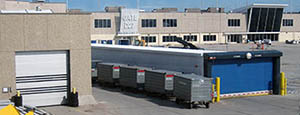
- Loading Dock
Rugged design & secure seal for oversized openings.
-
-
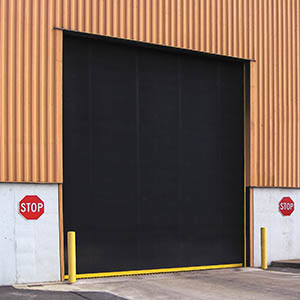
- Large Openings
Break-away functionality with rugged design seals oversized openings.
-
-
-
-
- Heavy Equipment
Withstands challenges of heavy equipment and fleet truck/car wash environments.
-
-
- Self-Storage
Fast opening speeds and reliable, durable construction keep facilities secure and protected.
-
-
- Industries
-
-
-
- Automotive Dealerships
Reduce energy costs, increase productivity and comfort and enhance customer perception.
-
-
- Cold Storage & Processing
Increase productivity and operational efficiency while reducing energy and maintenance costs.
-
-
- Parking
We offer solutions for Apartment / Condo & Loft, Standalone Parking Facilities and Office Buildings
-
-
-
-
- Food & Beverage
Doors specifically engineered for USDA/FDA and cGMP environments, and assured compliance for uncompromising performance.
-
-
- Mfg/Dist/Warehousing
A complete product line allows facilities to increase efficiency and safety and reduce maintenance and energy costs.
-
-
- Government
Ensure effective security and environmental controls are maintained for critical government operations.
-
-
-
-
- Transit
Keep operations running smoothly and efficient while reducing energy and maintenance costs.
-
-
- Pharma, Nutraceutical & Biotech
Doors that offer quick, secure access, environmental control and reliability for life science facilities.
-
-
- Support Resources
- Parts
- Contact Us
- Blog/News
- Why Rytec
- Sales Rep Locator
- Careers
- Dealers
- Architectural Resources












What Is a Screw Conveyor and How Does It Work?
A Screw Conveyor is a mechanical device that moves bulk materials through a trough or enclosed tube. Its rotating helical flight, commonly called an auger, pushes material forward as the shaft turns. The concept looks simple. The design is not.
Bulk-solids pioneer Andrew Jenike expressed a useful warning: “Bulk solids are not fluids.” This principle explains why Screw Conveyor performance depends on material behavior, not only motor power. Flour, grain, ash, pellets, and wet sludge can travel differently through the same equipment. Each material may require a different flight pitch, diameter, speed, or trough arrangement.
Inside the conveyor, the screw flight creates controlled movement. Gravity keeps the material near the bottom, while rotation carries it toward the discharge point. A direct drive may suit short, steady applications. A geared drive can provide stronger torque for dense or difficult materials. Small design choices matter.
Clearances matter too.
If the flight rubs against the trough, wear increases. If the conveyor runs too fast, the material may churn instead of moving smoothly. Poor inlet design can create uneven loading, product damage, or sudden motor overloads. These problems are often blamed on the conveyor itself. Sometimes, the real mistake began during material testing or installation.
This guide explains what a Screw Conveyor is, how it works, and where it performs best. It also examines common designs, operating limits, maintenance points, and practical selection factors. Some applications remain difficult to predict. Careful testing is still wiser than relying on a standard formula alone.
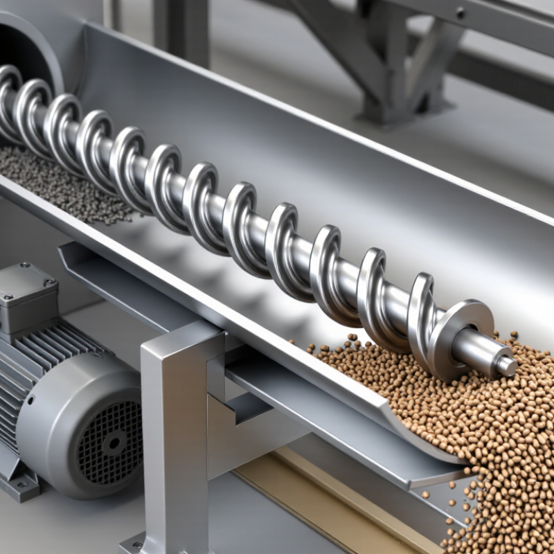
Table of Contents [Hide]
What Is a Screw Conveyor?
What Is a Screw Conveyor?
A screw conveyor is a mechanical device that moves bulk materials through a trough or enclosed tube. Its main part is a rotating helical blade, often called a screw or auger. A motor and gearbox turn the screw at a controlled speed. Material enters through an inlet, then the rotating flight pushes it toward the discharge point. Depending on its design, the conveyor can move powders, grains, pellets, ash, or damp industrial materials. It works horizontally, at an incline, and sometimes vertically.
The conveyor’s performance depends on screw diameter, pitch, rotation speed, and material behavior. A wider screw can carry more volume, while a slower speed may reduce dust and product damage. In practical operation, uneven feeding can cause surging or blockage. Moist material may stick to the flighting. This is easy to overlook. Regular checks should cover bearings, seals, motor load, and buildup inside the trough. A screw conveyor is reliable, but it is not suitable for every material or distance.
Tips: Match the screw design to the material before installation. Check moisture, temperature, density, and particle size. Keep guards secured and isolate power before maintenance. A short test run can reveal vibration, unusual noise, or poor discharge flow. Even experienced operators should review the layout when conditions change.