
- High-Performance Doors
-
- Applications
-
-
-
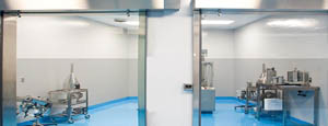
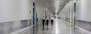
- Clean Room
Stainless steel or composite materials help maintain clean rooms.
-
-
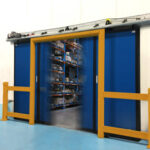
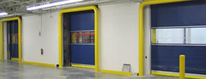
- Coolers
Quick opening speeds & tight seals for temperature control.
-
-
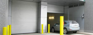
- Parking
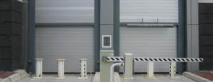
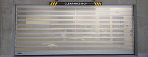
Improve security & traffic flow and enhance architectural style.
-
-
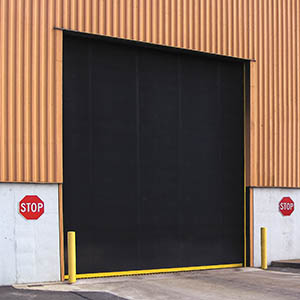
- Hurricane Zone
Withstand winds up to 175 mph and comply with the Florida Building Code.
-
-
-
-
- USDA / FDA / cGMP
Increase productivity & address stringent USDA, FDA & cGMP requirements.
-
-
- Freezers
High-speed & perimeter seals minimize the air exchange between areas.
-
-
- Security
High speed & durability ensure secure access.
-
-
- Ventilation
Perforated or screen door panels allow improved air circulation.
-
-
-
-
- Fire Station Emergency Response
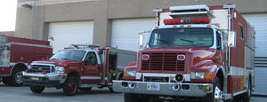
When time is of the essence, high speed and reliability are crucial.
-
-
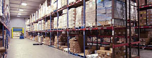
- Warehousing
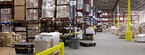
Fast cycle times and secure seals keep environments separated.
-
-
- Loading Dock
Rugged design & secure seal for oversized openings.
-
-
- Large Openings
Break-away functionality with rugged design seals oversized openings.
-
-
-
-
- Heavy Equipment
Withstands challenges of heavy equipment and fleet truck/car wash environments.
-
-
- Self-Storage
Fast opening speeds and reliable, durable construction keep facilities secure and protected.
-
-
- Industries
-
-
-
- Automotive Dealerships
Reduce energy costs, increase productivity and comfort and enhance customer perception.
-
-
- Cold Storage & Processing
Increase productivity and operational efficiency while reducing energy and maintenance costs.
-
-
- Parking
We offer solutions for Apartment / Condo & Loft, Standalone Parking Facilities and Office Buildings
-
-
-
-
- Food & Beverage
Doors specifically engineered for USDA/FDA and cGMP environments, and assured compliance for uncompromising performance.
-
-
- Mfg/Dist/Warehousing
A complete product line allows facilities to increase efficiency and safety and reduce maintenance and energy costs.
-
-
- Government
Ensure effective security and environmental controls are maintained for critical government operations.
-
-
-
-
- Transit
Keep operations running smoothly and efficient while reducing energy and maintenance costs.
-
-
- Pharma, Nutraceutical & Biotech
Doors that offer quick, secure access, environmental control and reliability for life science facilities.
-
-
- Support Resources
- Parts
- Contact Us
- Blog/News
- Why Rytec
- Sales Rep Locator
- Careers
- Dealers
- Architectural Resources











What Are Resonant Capacitors and How Do They Work?
What Are Resonant Capacitors and How Do They Work?
Resonant Capacitors are not ordinary energy-storage parts. They work with inductors to create a carefully controlled electrical rhythm. This rhythm is called resonance. At a selected frequency, the capacitor and inductor exchange energy repeatedly. The circuit can then shape voltage and current more smoothly.
Professor Robert W. Erickson, a respected power-electronics researcher, describes the principle clearly: “The resonant network shapes the switching waveforms.” That short statement explains much of the technology. A resonant capacitor may reduce switching losses, limit electrical stress, and support high-frequency operation. You can see its role in an induction heater, an LLC power supply, or a wireless charging system. During operation, the capacitor charges, discharges, and interacts with the magnetic field around the inductor. Timing matters.
Very much.
Choosing the wrong capacitance can shift the resonant frequency. The result may include excess heat, unstable output, or reduced efficiency. Temperature, voltage rating, dielectric losses, and parasitic effects also influence performance. These details are easy to overlook. I sometimes find simplified explanations too clean, because real circuits rarely behave perfectly. Component aging and layout resistance can change the expected result.
This introduction examines how Resonant Capacitors operate, where engineers use them, and why their design requires careful measurement. The goal is practical understanding, not just formulas. Expect clear examples, physical details, and a closer look at the compromises behind efficient resonant systems.
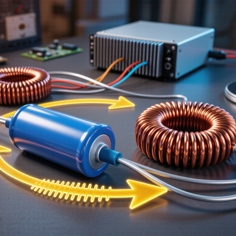
Table of Contents [Hide]
Definition and Core Principles of Resonant Capacitors
What Are Resonant Capacitors and How Do They Work?
Definition and Core Principles of Resonant Capacitors
A resonant capacitor is a capacitor selected to operate with an inductor at a target resonant frequency. It is not always a special component. Often, it is a carefully rated capacitor within an LC circuit. The circuit follows a simple relationship:
f = 1/(2π√LC)
Here, f represents frequency, L represents inductance, and C represents capacitance.
At resonance, the capacitor and inductor exchange stored energy. The capacitor stores energy in an electric field, while the inductor stores it in a magnetic field. Their reactances become equal and opposite, reducing the circuit’s net reactance. This can produce a strong circulating current, even when the external source current remains limited. Small errors matter. A 2% capacitance change can shift the operating frequency noticeably in a sensitive circuit.
On a workbench, engineers check capacitance, equivalent series resistance, voltage rating, and temperature behavior. A capacitor may work at low frequency but overheat at radio frequency because of internal losses.
Stray capacitance from a short PCB trace can also change the result. The ideal equation is clean; real hardware is not. Measurement equipment, layout, and component tolerances all influence resonance. Some designs therefore use adjustable capacitors or several capacitors in parallel. That approach improves tuning, but it adds connections and possible failure points.