
- High-Performance Doors
-
- Applications
-
-
-
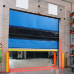
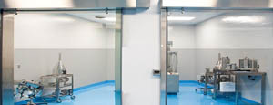
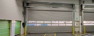
- Clean Room
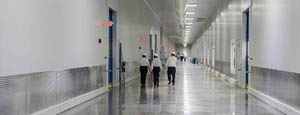
Stainless steel or composite materials help maintain clean rooms.
-
-
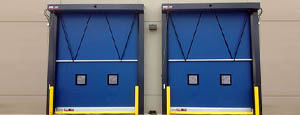
- Coolers
Quick opening speeds & tight seals for temperature control.
-
-
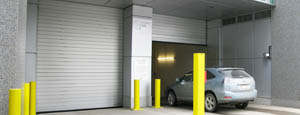
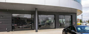
- Parking
Improve security & traffic flow and enhance architectural style.
-
-
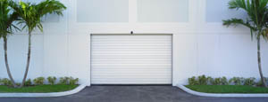
- Hurricane Zone
Withstand winds up to 175 mph and comply with the Florida Building Code.
-
-
-
-
- USDA / FDA / cGMP
Increase productivity & address stringent USDA, FDA & cGMP requirements.
-
-
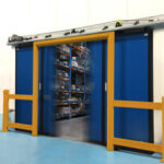
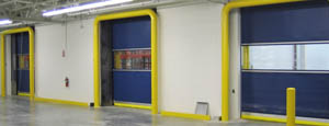
- Freezers
High-speed & perimeter seals minimize the air exchange between areas.
-
-
- Security
High speed & durability ensure secure access.
-
-
- Ventilation
Perforated or screen door panels allow improved air circulation.
-
-
-
-
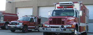
- Fire Station Emergency Response
When time is of the essence, high speed and reliability are crucial.
-
-
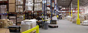
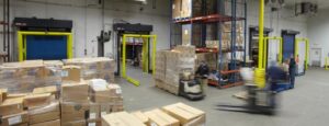
- Warehousing
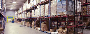
Fast cycle times and secure seals keep environments separated.
-
-
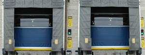
- Loading Dock
Rugged design & secure seal for oversized openings.
-
-
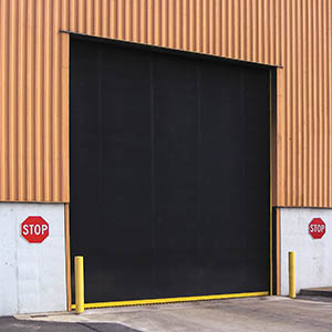
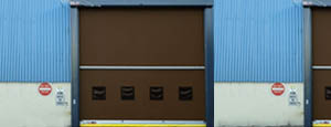
- Large Openings
Break-away functionality with rugged design seals oversized openings.
-
-
-
-
- Heavy Equipment
Withstands challenges of heavy equipment and fleet truck/car wash environments.
-
-
- Self-Storage
Fast opening speeds and reliable, durable construction keep facilities secure and protected.
-
-
- Industries
-
-
-
- Automotive Dealerships
Reduce energy costs, increase productivity and comfort and enhance customer perception.
-
-
- Cold Storage & Processing
Increase productivity and operational efficiency while reducing energy and maintenance costs.
-
-
- Parking
We offer solutions for Apartment / Condo & Loft, Standalone Parking Facilities and Office Buildings
-
-
-
-
- Food & Beverage
Doors specifically engineered for USDA/FDA and cGMP environments, and assured compliance for uncompromising performance.
-
-
- Mfg/Dist/Warehousing
A complete product line allows facilities to increase efficiency and safety and reduce maintenance and energy costs.
-
-
- Government
Ensure effective security and environmental controls are maintained for critical government operations.
-
-
-
-
- Transit
Keep operations running smoothly and efficient while reducing energy and maintenance costs.
-
-
- Pharma, Nutraceutical & Biotech
Doors that offer quick, secure access, environmental control and reliability for life science facilities.
-
-
- Support Resources
- Parts
- Contact Us
- Blog/News
- Why Rytec
- Sales Rep Locator
- Careers
- Dealers
- Architectural Resources




What Is a Rake System and How Does It Work?
A Rake System is a mechanical screening solution used to remove leaves, plastics, rags, and other coarse debris from water or wastewater channels. It protects pumps, gates, pipes, and downstream treatment equipment. In a typical installation, wastewater flows through fixed bars while a motor-driven rake travels along the screen face. The rake teeth capture debris, lift it above the waterline, and discharge it into a conveyor or collection bin.
The principle is simple. The design is not.
Screen spacing, channel depth, flow speed, and debris type determine performance. Excessive spacing can allow damaging materials to pass through. Narrow spacing improves capture but increases clogging, power demand, and maintenance. Sensors often monitor water-level differences across the screen. A rising differential head can trigger automatic raking before flooding occurs.
George Tchobanoglous, a leading wastewater-treatment authority, describes preliminary treatment as the stage intended to remove “coarse solids and other materials that may damage or interfere with subsequent treatment processes” (Wastewater Engineering: Treatment and Resource Recovery, 5th edition). That principle still guides modern rake-system design.
The U.S. Environmental Protection Agency’s 2022 Clean Watersheds Needs Survey, published in 2024, identified approximately $630.1 billion in documented wastewater infrastructure needs through 2041. The figure highlights the value of durable, maintainable equipment. The Water Environment Federation’s 2024 industry survey also shows continuing concern about aging assets, workforce shortages, and operational reliability.
A well-selected Rake System reduces manual cleaning and protects critical equipment. It cannot solve poor channel design. It also requires inspection, lubrication, and safe access. Small oversights matter. Performance depends on the whole system, not the rake alone.
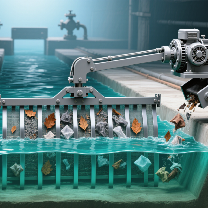
Table of Contents [Hide]
What Is a Rake System?
A rake system is a farm machine that gathers cut grass, hay, or straw into a narrow row called a windrow. This row makes baling, drying, and collection more efficient. Most systems use rotating wheels, spring tines, or parallel bars. As the machine moves forward, the rake lifts scattered forage and guides it toward one side or the center.
The working principle is simple. Ground wheels or a tractor power input turns the rake assembly. Flexible tines touch the field, but they should not scrape deeply into the soil. Excessive pressure can collect stones, increase contamination, and damage the crop.
The USDA National Agricultural Statistics Service reported about 119 million tons of U.S. all-hay production in its 2023 Crop Production report. That volume shows why consistent windrow formation matters during short weather windows. Small errors become expensive quickly.
Field experience still matters. Operators usually adjust rake height, travel speed, and rotor spacing after checking moisture and crop density. A dry, light crop needs gentler handling. Heavy forage may require slower travel.
The American Society of Agricultural and Biological Engineers emphasizes standardized testing for forage equipment, yet real fields rarely behave perfectly. Soil changes. Wind changes. Human judgment remains necessary. That is the part many equipment explanations miss.