
- High-Performance Doors
-
- Applications
-
-
-
- Clean Room
Stainless steel or composite materials help maintain clean rooms.
-
-
- Coolers
Quick opening speeds & tight seals for temperature control.
-
-
- Parking
Improve security & traffic flow and enhance architectural style.
-
-
- Hurricane Zone
Withstand winds up to 175 mph and comply with the Florida Building Code.
-
-
-
-
- USDA / FDA / cGMP
Increase productivity & address stringent USDA, FDA & cGMP requirements.
-
-
- Freezers
High-speed & perimeter seals minimize the air exchange between areas.
-
-
- Security
High speed & durability ensure secure access.
-
-
- Ventilation
Perforated or screen door panels allow improved air circulation.
-
-
-
-
- Fire Station Emergency Response
When time is of the essence, high speed and reliability are crucial.
-
-
- Warehousing
Fast cycle times and secure seals keep environments separated.
-
-
- Loading Dock
Rugged design & secure seal for oversized openings.
-
-
- Large Openings
Break-away functionality with rugged design seals oversized openings.
-
-
-
-
- Heavy Equipment
Withstands challenges of heavy equipment and fleet truck/car wash environments.
-
-
- Self-Storage
Fast opening speeds and reliable, durable construction keep facilities secure and protected.
-
-
- Industries
-
-
-
- Automotive Dealerships
Reduce energy costs, increase productivity and comfort and enhance customer perception.
-
-
- Cold Storage & Processing
Increase productivity and operational efficiency while reducing energy and maintenance costs.
-
-
- Parking
We offer solutions for Apartment / Condo & Loft, Standalone Parking Facilities and Office Buildings
-
-
-
-
- Food & Beverage
Doors specifically engineered for USDA/FDA and cGMP environments, and assured compliance for uncompromising performance.
-
-
- Mfg/Dist/Warehousing
A complete product line allows facilities to increase efficiency and safety and reduce maintenance and energy costs.
-
-
- Government
Ensure effective security and environmental controls are maintained for critical government operations.
-
-
-
-
- Transit
Keep operations running smoothly and efficient while reducing energy and maintenance costs.
-
-
- Pharma, Nutraceutical & Biotech
Doors that offer quick, secure access, environmental control and reliability for life science facilities.
-
-
- Support Resources
- Parts
- Contact Us
- Blog/News
- Why Rytec
- Sales Rep Locator
- Careers
- Dealers
- Architectural Resources

























How to Choose the Right Relay Transmitter?
Choosing the right Relay Transmitter is not simply a matter of comparing prices or selecting the longest communication range. The correct device must match your equipment, environment, signal type, and operating goals. A transmitter used beside a hot industrial motor may need different protection than one installed in a clean control cabinet. Small details matter.
In practical applications, I have found that many selection mistakes begin with unclear requirements. Confirm the input signal first, such as dry contact, voltage, current, or a digital protocol. Then check output behavior, transmission distance, power supply, response time, and mounting method. Wireless models also require careful attention to frequency, antenna placement, interference, and network stability. A strong signal on paper may weaken behind concrete walls or metal enclosures.
Safety matters more than convenience.
Review the manufacturer’s technical documentation and verify relevant certifications for your region. Check operating temperature, ingress protection, electrical isolation, and failure response. These specifications can reveal whether a product suits a factory floor, remote pump station, building system, or laboratory environment. Do not rely on marketing language alone.
No checklist is perfect. Field conditions often expose problems that testing misses. For that reason, compare real measurements with datasheet claims, ask suppliers for application guidance, and consider a controlled trial before large-scale installation. The best Relay Transmitter balances dependable performance, maintainability, compatibility, and future expansion. A cheaper option may appear attractive, yet its hidden wiring changes, battery replacements, or signal failures can increase long-term costs. Careful selection creates a safer, clearer, and more reliable control system.
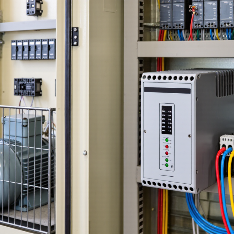
Table of Contents [Hide]
Understanding the Role and Operating Principles of Relay Transmitters
A relay transmitter connects field signals with control systems. Its relay monitors an input, such as temperature, pressure, or liquid level. When the signal reaches a set point, the relay changes its contact state. This action can start equipment, trigger an alarm, or protect a circuit. At the same time, the transmitter may convert the measured value into a standardized output, such as 4–20 mA or a digital signal. Isolation is also important. It helps prevent electrical noise from traveling between the sensor and controller.
Choosing the right relay transmitter requires more than checking the measurement range. Confirm the input type, output signal, contact rating, response time, and power supply. Check the installation environment too. Moisture, vibration, heat, and limited cabinet space can affect performance. In field testing, wiring errors often cause more trouble than device failure. Real installations are less tidy than diagrams. I have also found that a generous range is not always better; it may reduce useful resolution. Review the process limits and select a practical operating span.
Tips: Test the relay at normal and fault conditions. Verify whether the contact is normally open or normally closed. Leave space for ventilation and maintenance. Record the settings clearly. If signal noise appears, inspect grounding and cable routing before replacing components. A second review is worthwhile. Small assumptions can become expensive mistakes.
How to Choose the Right Relay Transmitter? - Understanding the Role and Operating Principles of Relay Transmitters
| Selection Dimension | What It Means | Common Options or Typical Values | Operating Principle | Selection Guidance |
|---|---|---|---|---|
| Basic Function | A relay transmitter transfers a control signal from an input circuit to an electrically isolated output circuit. | Signal switching, circuit isolation, alarm transmission, interlocking, and remote control | An input energizes a coil or semiconductor control stage, which changes the state of one or more output contacts or switching channels. | Choose a relay transmitter when isolation, contact multiplication, or switching a different voltage level is required. |
| Operating Technology | The internal method used to switch the output. | Electromechanical relay, solid-state relay, or hybrid relay | Electromechanical types use an energized coil and moving contacts. Solid-state types use semiconductor devices without mechanical contact movement. | Use electromechanical technology for broad load compatibility and galvanic contact switching. Use solid-state technology for high switching frequency, silent operation, and long mechanical life. |
| Input Signal Type | The electrical signal that activates the relay transmitter. | Digital voltage, dry contact, transistor output, pulse signal, or analog threshold input | The input circuit detects a voltage, current, or contact state and drives the relay switching element when the specified threshold is reached. | Match the input type to the controller output. A dry-contact input should not be connected to a powered output unless the device is designed for it. |
| Input Voltage | The nominal voltage required by the input or relay coil. | Common control levels include 5 V DC, 12 V DC, 24 V DC, 48 V DC, 110 V AC, and 230 V AC | The input circuit converts the applied control voltage into magnetic, optical, or electronic actuation. | Confirm the nominal voltage, allowable tolerance, polarity requirements, and whether the input is AC or DC before installation. |
| Input Current and Power | The current or power consumed by the input circuit during activation. | Typically from a few milliamperes for electronic inputs to several hundred milliamperes for larger coils | Coil-based devices draw current to create a magnetic field, while electronic devices use an input circuit to control a semiconductor switch. | Check the controller’s maximum output current. For low-power digital outputs, select a low-consumption input or use an interposing driver. |
| Output Contact Form | The electrical arrangement of the relay contacts. | Normally open (NO), normally closed (NC), changeover (CO/SPDT), DPDT, or multi-channel configurations | When the relay changes state, the common terminal connects to either the NO or NC terminal according to the contact arrangement. | Choose NO for loads that should be off by default, NC for fail-safe monitoring circuits, and changeover contacts when both states are needed. |
| Number of Channels | The number of independent input-output switching circuits in one device. | Single-channel, dual-channel, 4-channel, 8-channel, or higher-density modules | Each channel provides a separate switching path, although some modules may share power, commons, or protective components. | Select the channel count based on system expansion needs, cabinet space, wiring simplicity, and required isolation between channels. |
| Output Load Type | The kind of electrical load controlled by the relay contacts. | Resistive heaters, lamps, solenoid valves, motors, contactor coils, alarms, and electronic inputs | Relay contacts open or close the load circuit; the load’s inrush current and switching behavior determine contact stress. | Evaluate both steady-state current and inrush current. Motors, lamps, transformers, and solenoids may require derating or suppression. |
| Contact Rating | The maximum voltage and current the output contacts can safely switch under specified conditions. | Ratings vary by load type; common control applications use currents from signal level up to several amperes | The contacts must interrupt or carry current without excessive heating, arcing, welding, or loss of insulation. | Use the manufacturer’s rating for the actual AC or DC load. A contact rating for resistive loads may not apply to motors or inductive loads. |
| Switching Voltage | The maximum voltage present across the output circuit during operation. | Low-voltage DC, control-level AC, and higher industrial control voltages, subject to the device rating | Contact spacing, insulation system, and arc suppression determine the voltage the relay can interrupt safely. | Verify the rated voltage for the specific contact configuration and pollution environment. AC and DC interruption capability are not identical. |
| Electrical Isolation | The separation between input, output, and sometimes channel-to-channel circuits. | Galvanic isolation through contacts, transformer coupling, or optocouplers; isolation ratings are device-specific | Isolation prevents the output load voltage from directly reaching the control electronics, provided creepage, clearance, and insulation limits are respected. | Choose a device with separate input-output and channel-to-channel isolation where ground-loop prevention, safety, or different voltage domains are involved. |
| Response Time | The delay between input activation or release and the corresponding output change. | Electromechanical relays commonly operate in milliseconds; solid-state devices are generally faster | Mechanical movement, contact bounce, electronic filtering, and semiconductor turn-on characteristics contribute to the delay. | For high-speed counting, pulse generation, or rapid machine control, use a specified high-speed solid-state or electronic output rather than a general-purpose mechanical relay. |
| Contact Bounce | Brief unwanted transitions that occur when mechanical contacts open or close. | Present in electromechanical contacts; generally absent in solid-state switching | Physical contact surfaces may make and break several times before settling into a stable state. | Use debounce logic, a timer, or a suitable interface when the receiving circuit is sensitive to multiple transitions. |
| Switching Frequency | How often the relay can operate within its electrical and mechanical limits. | Low to moderate frequency for mechanical relays; higher frequency capability for solid-state designs | Each mechanical operation causes contact wear, while semiconductor switching is primarily limited by heat, voltage, and current stress. | Estimate the number of operations per hour and expected service life. Avoid using a mechanical relay for continuously repeated high-frequency switching. |
| Mechanical Life | The number of operations possible without an electrical load. | Often much higher than electrical life because there is little contact arcing under no-load conditions | Mechanical wear affects the armature, spring, bearings, and contact movement even when the load current is absent. | Compare mechanical life with electrical life; the electrical rating and load type usually determine the practical service interval. |
| Electrical Life | The expected number of switching cycles under a specified voltage, current, and load type. | Load-dependent and typically lower than mechanical life | Arcing, contact erosion, contact welding, and thermal stress gradually reduce switching reliability. | Use load-specific life data rather than relying only on the maximum current printed on a product label. |
| Inductive Load Protection | Measures used to limit voltage spikes produced when an inductive load is switched off. | Flyback diode for DC coils, RC snubber, varistor, or dedicated surge suppressor | Inductors resist sudden changes in current and can generate a high reverse-voltage transient at turn-off. | Install suppression close to the inductive load. A diode is suitable for many DC coils but changes the release behavior and must be correctly polarized. |
| Fail-Safe Behavior | The output state adopted after loss of input power, control wiring, or device power. | De-energized-safe, energized-safe, normally open, normally closed, or alarm-on-loss configurations | The contact arrangement and relay energization logic determine whether a fault produces an alarm or an apparently normal state. | For emergency or alarm circuits, select the state that exposes loss of power or wiring integrity instead of masking the fault. |
| Temperature Range | The ambient temperature range in which the relay transmitter operates within specification. | Industrial designs commonly cover sub-zero to elevated cabinet temperatures; the exact range is device-specific | Temperature affects coil resistance, contact capacity, insulation performance, semiconductor leakage, and heat dissipation. | Account for enclosure temperature, nearby heat sources, ventilation, and output derating at high ambient temperatures. |
| Mounting and Wiring | The physical installation method and terminal arrangement. | DIN-rail, panel, socket-mounted, PCB-mounted, screw terminal, spring terminal, or pluggable terminal | The mechanical interface secures the device while the terminals maintain the input, output, and protective connections. | Choose a mounting style compatible with the control cabinet, conductor size, maintenance method, and available clearance. |
| Protection and Environment | Resistance to dust, moisture, vibration, shock, and electrical interference. | Enclosed or sealed relay construction, protective coatings, vibration-resistant terminals, and specified ingress protection | Sealing and enclosure design reduce contamination, while mechanical retention and filtering improve reliability in harsh environments. | Check the required enclosure protection, vibration level, humidity, corrosive atmosphere, and electromagnetic environment. |
| Standards and Compliance | Safety and performance requirements relevant to relay construction and application. | Applicable low-voltage equipment, relay, insulation, EMC, and functional-safety requirements | Standards define conditions such as insulation coordination, dielectric strength, temperature rise, switching endurance, and electromagnetic compatibility. | Specify the standards required by the installation location, industry, voltage level, and safety classification before selecting the device. |
| Best Application Fit | The type of task for which the relay transmitter is most appropriate. | PLC interposing, alarm output, motor contactor control, signal conversion, safety interlocking, and remote status indication | The relay provides a controlled electrical interface between a low-power control system and a separate load or field circuit. | Prioritize electrical compatibility, isolation, load behavior, switching frequency, fault response, and environmental conditions over physical size alone. |