
- High-Performance Doors
-
- Applications
-
-
-
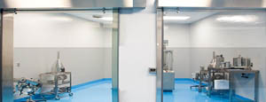
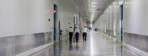
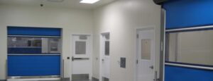
- Clean Room
Stainless steel or composite materials help maintain clean rooms.
-
-
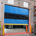
- Coolers
Quick opening speeds & tight seals for temperature control.
-
-
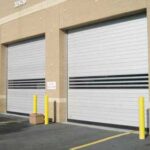
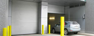
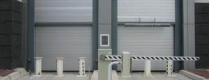
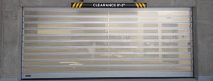
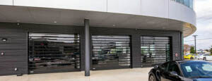
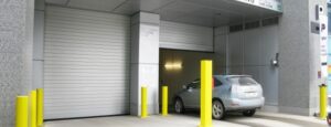
- Parking
Improve security & traffic flow and enhance architectural style.
-
-
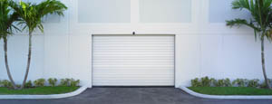
- Hurricane Zone
Withstand winds up to 175 mph and comply with the Florida Building Code.
-
-
-
-
- USDA / FDA / cGMP
Increase productivity & address stringent USDA, FDA & cGMP requirements.
-
-
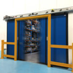
- Freezers
High-speed & perimeter seals minimize the air exchange between areas.
-
-
- Security
High speed & durability ensure secure access.
-
-
- Ventilation
Perforated or screen door panels allow improved air circulation.
-
-
-
-
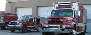
- Fire Station Emergency Response
When time is of the essence, high speed and reliability are crucial.
-
-
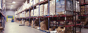
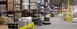
- Warehousing
Fast cycle times and secure seals keep environments separated.
-
-
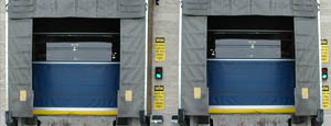
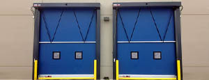
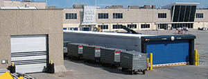
- Loading Dock
Rugged design & secure seal for oversized openings.
-
-
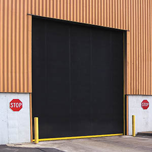
- Large Openings
Break-away functionality with rugged design seals oversized openings.
-
-
-
-
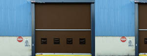
- Heavy Equipment
Withstands challenges of heavy equipment and fleet truck/car wash environments.
-
-
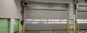
- Self-Storage
Fast opening speeds and reliable, durable construction keep facilities secure and protected.
-
-
- Industries
-
-
-
- Automotive Dealerships
Reduce energy costs, increase productivity and comfort and enhance customer perception.
-
-
- Cold Storage & Processing
Increase productivity and operational efficiency while reducing energy and maintenance costs.
-
-
- Parking
We offer solutions for Apartment / Condo & Loft, Standalone Parking Facilities and Office Buildings
-
-
-
-
- Food & Beverage
Doors specifically engineered for USDA/FDA and cGMP environments, and assured compliance for uncompromising performance.
-
-
- Mfg/Dist/Warehousing
A complete product line allows facilities to increase efficiency and safety and reduce maintenance and energy costs.
-
-
- Government
Ensure effective security and environmental controls are maintained for critical government operations.
-
-
-
-
- Transit
Keep operations running smoothly and efficient while reducing energy and maintenance costs.
-
-
- Pharma, Nutraceutical & Biotech
Doors that offer quick, secure access, environmental control and reliability for life science facilities.
-
-
- Support Resources
- Parts
- Contact Us
- Blog/News
- Why Rytec
- Sales Rep Locator
- Careers
- Dealers
- Architectural Resources



How to Choose the Right Power Breaker?
Choosing the right Power Breaker is a practical safety decision, not simply a matter of matching amperage. The breaker must suit the circuit’s voltage, expected load, available fault current, conductor size, and operating environment. A mismatch may cause nuisance trips or leave equipment inadequately protected. Small details matter.
NFPA’s Electrical Fires report, using U.S. data from 2015–2019, estimated an annual average of 31,647 home structure fires involving electrical failure or malfunction. Those fires were associated with 425 civilian deaths and $1.3 billion in direct property damage each year. These figures do not mean a breaker alone prevents every electrical fire. They do show why selection deserves care. A breaker’s interrupting rating, pole count, and trip characteristics all matter, alongside the circuit design.
For product selection, compare manufacturer documentation with applicable standards, such as UL 489 in the United States or IEC 60947-2 for relevant circuit breakers. Confirm the system voltage and fault-current rating rather than relying on a familiar label or frame size. A specification sheet can make this seem straightforward; I would not treat it as the whole answer. Installation conditions and local requirements can change what is appropriate. When ratings or compatibility are unclear, have a qualified electrical professional verify the choice before installation. A careful check beats a guess.
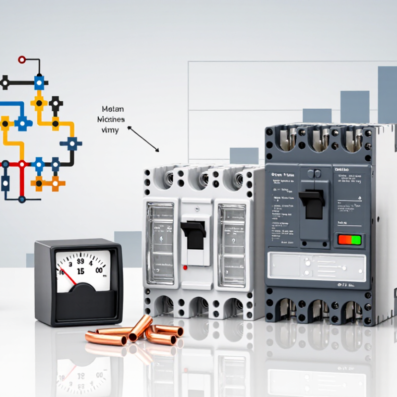
Table of Contents [Hide]
Identify Load Current and Apply the 125% Continuous-Load Rule
How to Choose the Right Power Breaker?
Start with the load current, not the breaker label. Under NFPA 70, a continuous load operates for three hours or longer and must be rated at 125% of its calculated value. For example, a circuit with 32 amperes of noncontinuous load and 16 amperes of continuous lighting load requires 52 amperes: 32 + (16 × 1.25). A 50-ampere breaker would be undersized for that calculation.
The conductor must also support the selected breaker. Check terminal temperature ratings, ambient temperature, conductor grouping, voltage, pole count, and available fault current. The breaker’s interrupting rating must meet or exceed the prospective fault current at the panel. NFPA Research reported that electrical distribution and lighting equipment contributed to approximately 35,150 home structure fires annually from 2015–2019, with about 470 civilian deaths and 1,100 injuries. Protection details matter.
Real panels rarely behave like a clean spreadsheet. Motors, transformers, and power supplies can create starting surges, while warm enclosures reduce conductor capacity. A larger breaker is not automatically safer. In a field review, the load schedule may show 48 amperes, but later-added equipment can quietly change the result. Recheck measured current, continuous operation, and conductor derating before final selection. The calculation can be simple. The installation is not.