
- High-Performance Doors
-
- Applications
-
-
-
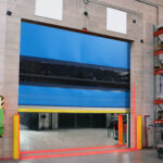
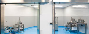
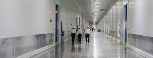
- Clean Room
Stainless steel or composite materials help maintain clean rooms.
-
-
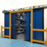
- Coolers
Quick opening speeds & tight seals for temperature control.
-
-
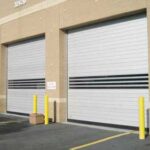
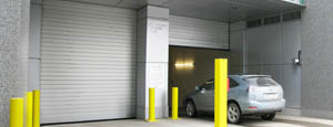
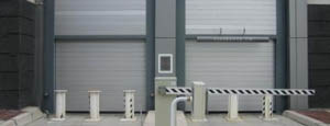
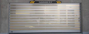
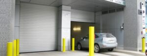
- Parking
Improve security & traffic flow and enhance architectural style.
-
-
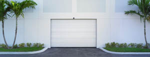
- Hurricane Zone
Withstand winds up to 175 mph and comply with the Florida Building Code.
-
-
-
-
- USDA / FDA / cGMP
Increase productivity & address stringent USDA, FDA & cGMP requirements.
-
-
- Freezers
High-speed & perimeter seals minimize the air exchange between areas.
-
-
- Security
High speed & durability ensure secure access.
-
-
- Ventilation
Perforated or screen door panels allow improved air circulation.
-
-
-
-
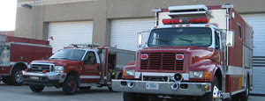
- Fire Station Emergency Response
When time is of the essence, high speed and reliability are crucial.
-
-
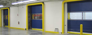
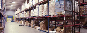
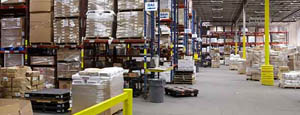
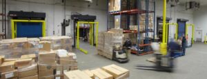
- Warehousing
Fast cycle times and secure seals keep environments separated.
-
-
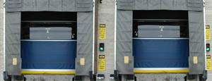
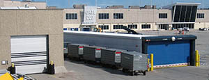
- Loading Dock
Rugged design & secure seal for oversized openings.
-
-
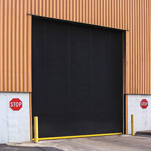
- Large Openings
Break-away functionality with rugged design seals oversized openings.
-
-
-
-
- Heavy Equipment
Withstands challenges of heavy equipment and fleet truck/car wash environments.
-
-
- Self-Storage
Fast opening speeds and reliable, durable construction keep facilities secure and protected.
-
-
- Industries
-
-
-
- Automotive Dealerships
Reduce energy costs, increase productivity and comfort and enhance customer perception.
-
-
- Cold Storage & Processing
Increase productivity and operational efficiency while reducing energy and maintenance costs.
-
-
- Parking
We offer solutions for Apartment / Condo & Loft, Standalone Parking Facilities and Office Buildings
-
-
-
-
- Food & Beverage
Doors specifically engineered for USDA/FDA and cGMP environments, and assured compliance for uncompromising performance.
-
-
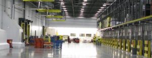
- Mfg/Dist/Warehousing
A complete product line allows facilities to increase efficiency and safety and reduce maintenance and energy costs.
-
-
- Government
Ensure effective security and environmental controls are maintained for critical government operations.
-
-
-
-
- Transit
Keep operations running smoothly and efficient while reducing energy and maintenance costs.
-
-
- Pharma, Nutraceutical & Biotech
Doors that offer quick, secure access, environmental control and reliability for life science facilities.
-
-
- Support Resources
- Parts
- Contact Us
- Blog/News
- Why Rytec
- Sales Rep Locator
- Careers
- Dealers
- Architectural Resources

What Are High Speed Lifts and How Do They Work?
High Speed Lifts are the quiet arteries of modern vertical cities. They carry passengers through hundreds of metres in seconds, while controlling acceleration, vibration, pressure, and energy use. A lift rated at 10 metres per second still needs careful stopping. Comfort matters as much as speed.
The Council on Tall Buildings and Urban Habitat reported 202 buildings above 200 metres completed worldwide in 2023. That figure shows why vertical transportation remains essential in dense urban development. Fortune Business Insights valued the global elevator market at approximately USD 97.34 billion in 2023, with continued growth expected through 2032. These figures describe opportunity, not guaranteed performance. Market forecasts can change.
Antony Wood, a leading tall-building specialist and former CTBUH executive director, has stated, “Without the elevator, there would be no skyscraper.” His observation remains highly relevant to High Speed Lifts. Modern systems use traction machines, counterweights, advanced guide rails, and regenerative drives. Double-deck cabins and destination-control software can also reduce waiting times. Inside the car, pressure changes may affect passengers near tall buildings’ upper floors. Designers therefore use staged acceleration, aerodynamic cabin shapes, and pressure-control strategies.
The numbers look impressive.
Yet speed alone is a weak measure. A technically fast lift can still feel slow when dispatching is poorly managed. It can also waste energy without intelligent control. Understanding how High Speed Lifts work requires more than reading a specification sheet. It requires examining safety systems, passenger comfort, building height, traffic patterns, maintenance records, and real operating conditions. That is where attractive claims deserve careful questioning.
Table of Contents [Hide]
Defining High-Speed Lifts: Speeds Above 2.5 m/s in Modern Buildings
High-speed lifts are vertical transport systems designed to travel above 2.5 m/s. This threshold is widely used in modern building discussions. It separates ordinary passenger lifts from systems serving tall towers and busy commercial spaces. CIBSE Guide D: Transportation Systems in Buildings explains that rated speed must be assessed with handling capacity, interval time, and passenger demand. Speed alone is not enough. A lift moving at 6 m/s can still perform poorly during morning traffic.
The lift accelerates through controlled motor torque and variable-frequency drives. Sensors monitor position, load, vibration, and door movement continuously. The controller adjusts speed between floors, then reduces acceleration before arrival. This protects passenger comfort and limits sudden pressure changes. According to the CTBUH Skyscraper Center, a supertall building has recorded lift speeds of about 20.5 m/s. That figure shows the engineering ceiling can be extremely high. However, real projects often select lower speeds to balance cost, energy use, shaft height, and maintenance access. The definition is helpful, but not perfect.
Tips: Check the complete traffic study before choosing a rated speed. Review five-minute handling capacity, average waiting time, and peak passenger flow. CIBSE recommends evaluating these indicators together. Ask for measured vibration data, not only brochure figures. Small errors in population estimates can create long queues. This is where planning becomes difficult. Local observation still matters, because occupant habits rarely match a clean spreadsheet.