
- High-Performance Doors
-
- Applications
-
-
-
- Clean Room
Stainless steel or composite materials help maintain clean rooms.
-
-
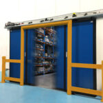
- Coolers
Quick opening speeds & tight seals for temperature control.
-
-
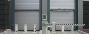
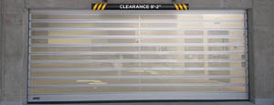
- Parking
Improve security & traffic flow and enhance architectural style.
-
-
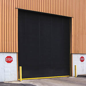
- Hurricane Zone
Withstand winds up to 175 mph and comply with the Florida Building Code.
-
-
-
-
- USDA / FDA / cGMP
Increase productivity & address stringent USDA, FDA & cGMP requirements.
-
-
- Freezers
High-speed & perimeter seals minimize the air exchange between areas.
-
-
- Security
High speed & durability ensure secure access.
-
-
- Ventilation
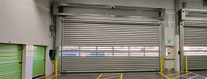
Perforated or screen door panels allow improved air circulation.
-
-
-
-
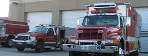
- Fire Station Emergency Response
When time is of the essence, high speed and reliability are crucial.
-
-
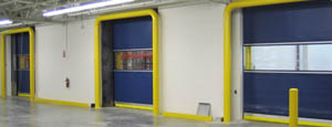
- Warehousing
Fast cycle times and secure seals keep environments separated.
-
-
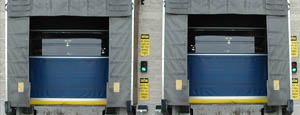
- Loading Dock
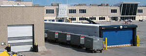
Rugged design & secure seal for oversized openings.
-
-
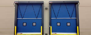
- Large Openings
Break-away functionality with rugged design seals oversized openings.
-
-
-
-
- Heavy Equipment
Withstands challenges of heavy equipment and fleet truck/car wash environments.
-
-
- Self-Storage
Fast opening speeds and reliable, durable construction keep facilities secure and protected.
-
-
- Industries
-
-
-
- Automotive Dealerships
Reduce energy costs, increase productivity and comfort and enhance customer perception.
-
-
- Cold Storage & Processing
Increase productivity and operational efficiency while reducing energy and maintenance costs.
-
-
- Parking
We offer solutions for Apartment / Condo & Loft, Standalone Parking Facilities and Office Buildings
-
-
-
-
- Food & Beverage
Doors specifically engineered for USDA/FDA and cGMP environments, and assured compliance for uncompromising performance.
-
-
- Mfg/Dist/Warehousing
A complete product line allows facilities to increase efficiency and safety and reduce maintenance and energy costs.
-
-
- Government
Ensure effective security and environmental controls are maintained for critical government operations.
-
-
-
-
- Transit
Keep operations running smoothly and efficient while reducing energy and maintenance costs.
-
-
- Pharma, Nutraceutical & Biotech
Doors that offer quick, secure access, environmental control and reliability for life science facilities.
-
-
- Support Resources
- Parts
- Contact Us
- Blog/News
- Why Rytec
- Sales Rep Locator
- Careers
- Dealers
- Architectural Resources
















What Is an Ebike Cable and How Does It Work?
An Ebike Cable is more than a simple wire linking two components. It may carry battery power, brake signals, display data, or motor commands. Some cables appear identical, yet their voltage ratings, connector designs, and communication protocols can differ sharply. That difference matters.
The market is expanding quickly. The International Energy Agency’s Global EV Outlook 2024 identifies electric two- and three-wheelers as the largest electrified road-vehicle segment by global stock. CONEBI’s European Bicycle Industry and Market Profile 2024 also shows how deeply e-bikes have entered everyday cycling across Europe. More bikes mean more attention to cable reliability, repairability, and safety. A loose connector can interrupt motor assistance beside a busy road. Moisture can enter a poorly sealed plug. Repeated handlebar movement can fatigue internal conductors.
Inside an Ebike Cable, copper conductors transmit electrical energy or digital signals. Insulation separates circuits. Connectors maintain contact under vibration. Some systems add shielding against electromagnetic interference. Cable length also matters, because excessive length can increase resistance and signal loss. It is not always obvious.
Industry guidance, including UL 2849-based electrical safety practices, emphasizes system-level evaluation rather than judging one cable alone. The battery, controller, charger, motor, and wiring must work together. This article explains what an Ebike Cable does, how signals and power travel through it, and which design details influence performance. The terminology is not perfectly standardized. That can create confusion, even among experienced buyers and technicians. A careful inspection remains essential.
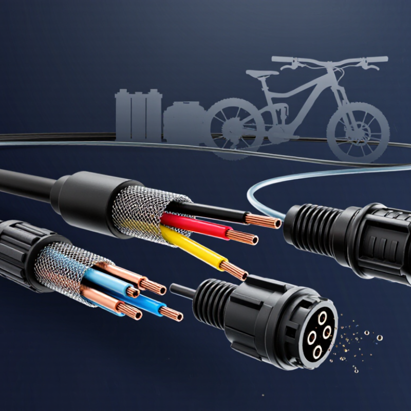
Table of Contents [Hide]
Ebike Cable Anatomy: Conductors, Insulation, Connectors, and IP Ratings
What Is an Ebike Cable and How Does It Work?
Ebike cables carry power and signals between the battery, controller, motor, display, and sensors. Inside each cable, copper conductors move electrical current or data. Thicker conductors usually handle higher current with less voltage loss. That detail matters.
Insulation surrounds the conductors and prevents short circuits, moisture contact, and accidental abrasion. Common insulation materials must remain flexible during steering and vibration. A cable may look strong, yet repeated bending near the handlebar can damage its internal strands. I have seen outer jackets remain intact while hidden conductors weaken. Small faults spread.
Connectors join cable sections and must match their pin layout, voltage, and signal purpose. A loose connector can cause intermittent power, display errors, or motor cutouts. Always check for bent pins, dirt, and incomplete locking before blaming the controller. Connector shape alone is not enough. Some similar-looking plugs carry different signals.
An IP rating describes resistance to dust and water under controlled testing. The first number measures solids, while the second measures water protection. A higher rating does not make a cable permanently waterproof. Pressure washing, damaged seals, and immersion can still allow water inside. Not always obvious. After riding in heavy rain, inspect low cable points and allow connectors to dry before reconnecting them. Wiring diagrams and service measurements provide better evidence than guesswork, although real-world wear can still challenge a perfect diagnosis.