
- High-Performance Doors
-
- Applications
-
-
-
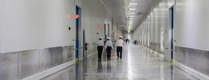
- Clean Room
Stainless steel or composite materials help maintain clean rooms.
-
-
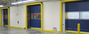
- Coolers
Quick opening speeds & tight seals for temperature control.
-
-
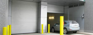
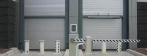
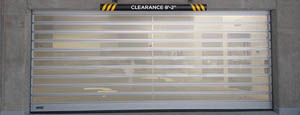
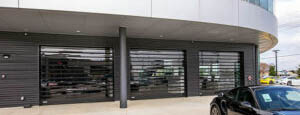
- Parking
Improve security & traffic flow and enhance architectural style.
-
-
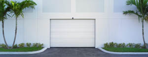
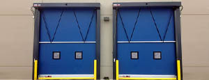
- Hurricane Zone
Withstand winds up to 175 mph and comply with the Florida Building Code.
-
-
-
-
- USDA / FDA / cGMP
Increase productivity & address stringent USDA, FDA & cGMP requirements.
-
-
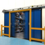
- Freezers
High-speed & perimeter seals minimize the air exchange between areas.
-
-
- Security
High speed & durability ensure secure access.
-
-
- Ventilation
Perforated or screen door panels allow improved air circulation.
-
-
-
-
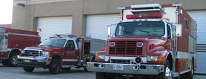
- Fire Station Emergency Response
When time is of the essence, high speed and reliability are crucial.
-
-
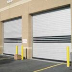
- Warehousing
Fast cycle times and secure seals keep environments separated.
-
-
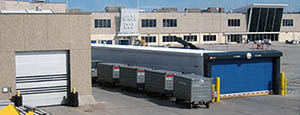
- Loading Dock
Rugged design & secure seal for oversized openings.
-
-
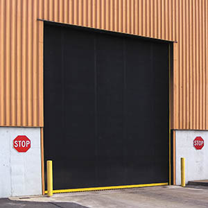
- Large Openings
Break-away functionality with rugged design seals oversized openings.
-
-
-
-
- Heavy Equipment
Withstands challenges of heavy equipment and fleet truck/car wash environments.
-
-
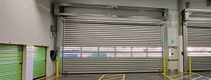
- Self-Storage
Fast opening speeds and reliable, durable construction keep facilities secure and protected.
-
-
- Industries
-
-
-
- Automotive Dealerships
Reduce energy costs, increase productivity and comfort and enhance customer perception.
-
-
- Cold Storage & Processing
Increase productivity and operational efficiency while reducing energy and maintenance costs.
-
-
- Parking
We offer solutions for Apartment / Condo & Loft, Standalone Parking Facilities and Office Buildings
-
-
-
-
- Food & Beverage
Doors specifically engineered for USDA/FDA and cGMP environments, and assured compliance for uncompromising performance.
-
-
- Mfg/Dist/Warehousing
A complete product line allows facilities to increase efficiency and safety and reduce maintenance and energy costs.
-
-
- Government
Ensure effective security and environmental controls are maintained for critical government operations.
-
-
-
-
- Transit
Keep operations running smoothly and efficient while reducing energy and maintenance costs.
-
-
- Pharma, Nutraceutical & Biotech
Doors that offer quick, secure access, environmental control and reliability for life science facilities.
-
-
- Support Resources
- Parts
- Contact Us
- Blog/News
- Why Rytec
- Sales Rep Locator
- Careers
- Dealers
- Architectural Resources










How to Choose a Wideband Blade Antenna?
Choosing a Wideband Blade Antenna is rarely a simple comparison of frequency ranges and attractive product images. The right choice depends on platform space, coverage needs, mounting conditions, and signal reliability.
A careful selection process starts with the mission, not with a promising product photograph. Define the operating bands, polarization, impedance, gain, and radiation pattern. Then examine the antenna’s real installation environment. A rooftop, vehicle roof, unmanned platform, and coastal enclosure create different challenges. Metal surfaces can change the pattern. Nearby cables may also introduce unwanted coupling.
Practical experience shows that datasheet bandwidth alone can mislead. Ask whether the stated range supports acceptable efficiency and stable performance. Check measured results, test methods, connector type, and environmental ratings. Look for evidence from recognized laboratories, manufacturer documentation, and applicable industry standards. A robust enclosure should withstand vibration, moisture, temperature changes, and repeated maintenance.
Installation details matter. A poorly bonded ground plane can reduce performance, even when the antenna itself is well designed. Cable loss deserves attention too. Every connector adds another possible failure point. Small details matter.
Cost should include brackets, cables, tuning, testing, and future replacement. I have seen specifications appear excellent until installation constraints changed the outcome. That possibility deserves honest consideration. The best antenna is not always the one with the widest advertised range. It is the one that delivers dependable coverage, manageable integration, and consistent results in the field. This guide explains how to evaluate those factors with practical judgment and technical discipline.
Table of Contents [Hide]
Define the operating band using ITU VHF (30–300 MHz) and UHF (300–3,000 MHz)
How to Choose a Wideband Blade Antenna?
Define the operating band before comparing blade antennas. ITU VHF spans 30–300 MHz, while UHF covers 300–3,000 MHz. These ranges differ greatly in wavelength, installation needs, and propagation behavior. A VHF design may need more physical length for efficient radiation. A UHF design can be smaller, but losses and connector quality become more noticeable. Choose an antenna covering your actual frequencies, not merely the entire label.
In field testing, I check the antenna’s measured return loss across the intended band. I also inspect the mounting surface, ground reference, cable routing, and nearby metalwork. A blade mounted on a vehicle roof may perform differently from one fixed to a narrow panel. Do not trust a wide frequency claim without test conditions. I once focused too heavily on bandwidth and overlooked poor cable placement. The result was unstable performance. That mistake still influences my selection process.
Tips: Write down the lowest and highest operating frequencies. Then identify the center frequency and required bandwidth. Check gain, polarization, power handling, connector type, and environmental sealing. For VHF, examine the available ground area carefully. For UHF, keep feed cables short and well routed. Measure the installed antenna when possible. A laboratory result may not match the final installation. Calibration matters. Real conditions matter more.
How to Choose a Wideband Blade Antenna? — Define the Operating Band Using ITU VHF (30–300 MHz) and UHF (300–3,000 MHz)
| Frequency Segment | Frequency Range | Approximate Wavelength | Typical Radio Uses | Blade Antenna Selection Focus | Expected Polarization | Installation Considerations | Key Trade-Off |
|---|---|---|---|---|---|---|---|
| Lower VHF | 30–88 MHz | 10.0–3.41 m | Land-mobile communications, public-safety radio, utility networks, and specialized low-band services. | Use a blade designed for physically long electrical length or incorporating suitable broadband matching. Confirm the specified lower frequency limit under the intended ground-plane condition. | Usually vertical for terrestrial mobile-radio systems. | Vehicle roof area, mast clearance, cable loss, and mechanical loading are important because the antenna is electrically short at the low end. | Lower frequencies generally require greater effective antenna length and may reduce compactness. |
| Upper VHF | 88–174 MHz | 3.41–1.72 m | FM broadcast reception, aviation communications, marine radio, public-safety systems, and land-mobile radio. | Check the exact operating sub-band, impedance, return-loss or VSWR specification, and whether the antenna is intended for transmit, receive, or both. | Vertical for most mobile and land-based communication applications; application-dependent for broadcast reception. | Keep the blade clear of nearby metal structures and route the coaxial cable away from high-current wiring where possible. | Wider coverage may require a matching network that can affect efficiency and power handling. |
| VHF–UHF Transition | 174–470 MHz | 1.72–0.638 m | Wideband public-safety, transportation, industrial, telemetry, and multi-service radio platforms. | Select a model whose continuous frequency specification covers the complete required band rather than relying only on separate nominal center frequencies. | Normally vertical for mobile radio; verify the system design before installation. | Vehicle body, mounting bracket, cable length, and connector quality can influence measured performance across the broad band. | Broad coverage improves flexibility but may produce varying efficiency and radiation patterns across frequency. |
| Lower UHF | 470–806 MHz | 0.638–0.372 m | UHF land-mobile radio, public-safety communications, industrial control, wireless data, and selected broadcast services. | Prioritize measured wideband VSWR, total efficiency, and power rating at the frequencies that carry the most traffic. | Typically vertical for terrestrial mobile systems. | At these frequencies, mounting location and nearby equipment can noticeably change the radiation pattern and impedance. | Compact dimensions are practical, but losses from materials, matching circuits, and connectors become more significant. |
| Upper UHF | 806–960 MHz | 0.372–0.313 m | Cellular, private mobile radio, public-safety broadband, telemetry, tracking, and short-range data systems. | Confirm compatibility with the required uplink and downlink ranges, connector type, isolation requirements, and simultaneous-transmit conditions. | Often vertical or system-defined by the radio network. | Maintain adequate separation from other antennas and conductive surfaces; use low-loss coaxial cable for longer runs. | Higher frequency supports smaller blades but is more sensitive to installation geometry and cable loss. |
| L-Band UHF | 960–1,300 MHz | 0.313–0.231 m | Navigation, aeronautical surveillance, satellite-related services, telemetry, and specialized wireless links. | Check whether the antenna specification covers the complete band continuously and whether the radiation pattern remains suitable for the intended platform. | Application-specific; commonly vertical for terrestrial links, but not universal. | Connector, radome material, mounting angle, and nearby electronics may have measurable effects at this range. | Compact size is an advantage, while pattern stability and installation tolerance require closer verification. |
| Upper UHF / Lower Microwave | 1,300–3,000 MHz | 0.231–0.100 m | Wireless broadband, satellite communications, radar-related systems, navigation, industrial telemetry, and short-range radio links. | Use an antenna specifically qualified for the required upper-frequency limit. Verify gain, efficiency, VSWR, pattern, and maximum input power at representative frequencies. | Defined by the communication system; do not assume vertical polarization. | Use carefully controlled mounting, high-quality connectors, and appropriately rated low-loss coaxial cable. Avoid sharp bends and unnecessary cable length. | Small physical size is possible, but feed-system loss, enclosure effects, and pattern variation become increasingly important. |
| Complete VHF Coverage | 30–300 MHz | 10.0–1.00 m | Multi-band VHF communications and platforms requiring coverage across several VHF services. | Choose a design with a published continuous operating range, not merely several separated passbands. Compare efficiency at the lowest required frequency. | Usually vertical for mobile and land-based radio systems. | A sufficiently large conductive ground plane and mechanically robust mounting are often necessary for consistent low-band performance. | Maximum flexibility may come with reduced efficiency at the lowest frequencies and a larger physical structure. |
| Complete UHF Coverage | 300–3,000 MHz | 1.00–0.100 m | Multi-service UHF platforms, broadband data terminals, monitoring equipment, and radio systems spanning several UHF allocations. | Confirm that the antenna is genuinely broadband across the required range and review efficiency, gain, pattern, and power data at multiple test frequencies. | System-dependent; polarization must match the radio link. | Installation details, radome properties, cable selection, antenna spacing, and electromagnetic compatibility should be assessed together. | Very broad frequency coverage can involve compromises in gain, efficiency, pattern uniformity, and power handling. |
Wavelength values are approximate and calculated using λ = c/f, where c is approximately 299,792,458 m/s. Actual antenna performance depends on the antenna design, ground plane, mounting structure, cable assembly, enclosure, and surrounding environment.