
- High-Performance Doors
-
- Applications
-
-
-
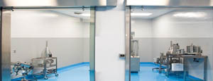
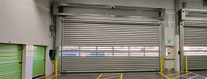
- Clean Room
Stainless steel or composite materials help maintain clean rooms.
-
-
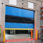
- Coolers
Quick opening speeds & tight seals for temperature control.
-
-
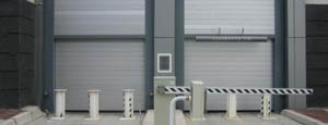
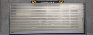
- Parking
Improve security & traffic flow and enhance architectural style.
-
-
- Hurricane Zone
Withstand winds up to 175 mph and comply with the Florida Building Code.
-
-
-
-
- USDA / FDA / cGMP
Increase productivity & address stringent USDA, FDA & cGMP requirements.
-
-
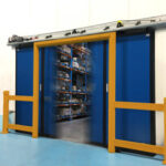
- Freezers
High-speed & perimeter seals minimize the air exchange between areas.
-
-
- Security
High speed & durability ensure secure access.
-
-
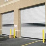
- Ventilation
Perforated or screen door panels allow improved air circulation.
-
-
-
-
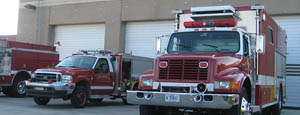
- Fire Station Emergency Response
When time is of the essence, high speed and reliability are crucial.
-
-
- Warehousing
Fast cycle times and secure seals keep environments separated.
-
-
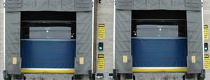
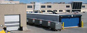
- Loading Dock
Rugged design & secure seal for oversized openings.
-
-
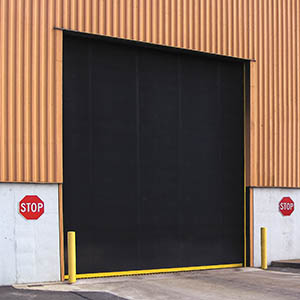
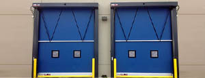
- Large Openings
Break-away functionality with rugged design seals oversized openings.
-
-
-
-
- Heavy Equipment
Withstands challenges of heavy equipment and fleet truck/car wash environments.
-
-
- Self-Storage
Fast opening speeds and reliable, durable construction keep facilities secure and protected.
-
-
- Industries
-
-
-
- Automotive Dealerships
Reduce energy costs, increase productivity and comfort and enhance customer perception.
-
-
- Cold Storage & Processing
Increase productivity and operational efficiency while reducing energy and maintenance costs.
-
-
- Parking
We offer solutions for Apartment / Condo & Loft, Standalone Parking Facilities and Office Buildings
-
-
-
-
- Food & Beverage
Doors specifically engineered for USDA/FDA and cGMP environments, and assured compliance for uncompromising performance.
-
-
- Mfg/Dist/Warehousing
A complete product line allows facilities to increase efficiency and safety and reduce maintenance and energy costs.
-
-
- Government
Ensure effective security and environmental controls are maintained for critical government operations.
-
-
-
-
- Transit
Keep operations running smoothly and efficient while reducing energy and maintenance costs.
-
-
- Pharma, Nutraceutical & Biotech
Doors that offer quick, secure access, environmental control and reliability for life science facilities.
-
-
- Support Resources
- Parts
- Contact Us
- Blog/News
- Why Rytec
- Sales Rep Locator
- Careers
- Dealers
- Architectural Resources












How to Choose the Right Festo Pneumatic Cylinder?
Choosing the right Festo Pneumatic Cylinder is not simply a matter of matching bore size and stroke length. A cylinder may fit the drawing yet fail under real factory conditions. Air pressure changes. Loads move unevenly. Dust collects around the rod seal.
Dr. Frank Melzer, former Chief Technology Officer at Festo, has said, “Digitalisation is not an end in itself; it must create customer value.” That principle also applies to pneumatic selection. The correct Festo Pneumatic Cylinder should solve a measurable motion problem, not merely add an impressive specification. This guide examines load direction, stroke distance, operating pressure, speed control, mounting style, and environmental exposure. It also considers sensors, cushioning, available installation space, and maintenance access.
Small details matter.
For example, a horizontal slide carrying a 12-kilogram fixture needs more than a simple force calculation. Friction, stopping impact, acceleration, and safety margin can change the result. A compact cylinder may work during testing, then hesitate after months of side loading. That uncomfortable possibility deserves attention. Engineers sometimes select the smallest model to reduce cost, but this choice can increase wear and downtime.
The following sections provide a practical selection path based on Festo documentation, workshop experience, and application-focused engineering judgment. Product data should still be checked against the latest manufacturer specifications. No guide replaces testing the cylinder under actual load, pressure, temperature, and cycle conditions. The best decision is usually the one that remains reliable when the machine is no longer new.
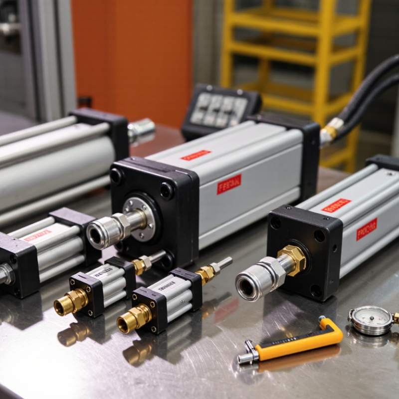
Table of Contents [Hide]
Define Load and Force Needs with F = pA at the Standard 6 bar
Choosing a pneumatic cylinder starts with the load, not the catalog. At the standard 6 bar, use F = pA, where pressure is 0.6 N/mm². Calculate piston area with A = πD²/4. A 32 mm bore provides about 482 N theoretically. A 50 mm bore provides approximately 1,178 N. These figures describe extension force before losses. They are not working guarantees.
Rod-side force is lower because the rod reduces effective area. Friction, pressure drop, seals, cushioning, and acceleration also consume force. In practical testing, a cylinder may stall when the calculation looks perfect. That assumption needs checking. Measure the real load, travel speed, mounting position, and cycle frequency. For vertical loads, include gravity and the force needed to start movement. Select a suitable force margin after testing, rather than guessing from bore size alone.
Compressed air quality also affects reliability. The U.S. Department of Energy’s Improving Compressed Air System Performance guidance reports that leaks can waste 20–30% of compressor output. A leaking fitting near the cylinder can therefore reduce available force during demanding cycles. ISO 15552 dimensions help standardize cylinder selection, but they do not replace system verification. Check pressure at the cylinder port while moving, not only at the compressor gauge. Record the lowest reading. Then compare it with the force required at that exact moment.