
- High-Performance Doors
-
- Applications
-
-
-
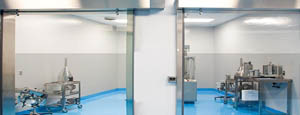
- Clean Room
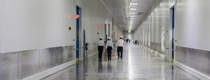
Stainless steel or composite materials help maintain clean rooms.
-
-
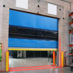
- Coolers
Quick opening speeds & tight seals for temperature control.
-
-
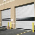
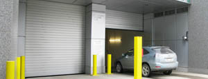
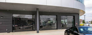
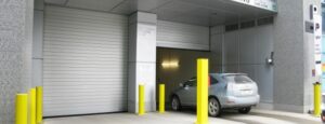
- Parking
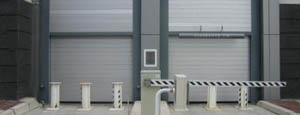
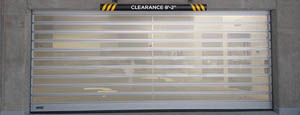
Improve security & traffic flow and enhance architectural style.
-
-
- Hurricane Zone
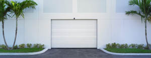
Withstand winds up to 175 mph and comply with the Florida Building Code.
-
-
-
-
- USDA / FDA / cGMP
Increase productivity & address stringent USDA, FDA & cGMP requirements.
-
-
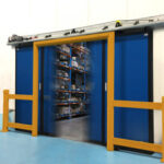
- Freezers
High-speed & perimeter seals minimize the air exchange between areas.
-
-
- Security
High speed & durability ensure secure access.
-
-
- Ventilation
Perforated or screen door panels allow improved air circulation.
-
-
-
-
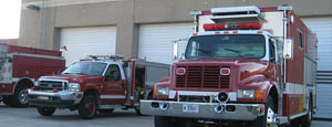
- Fire Station Emergency Response
When time is of the essence, high speed and reliability are crucial.
-
-
- Warehousing
Fast cycle times and secure seals keep environments separated.
-
-
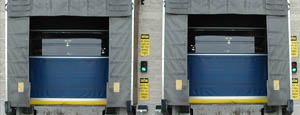
- Loading Dock
Rugged design & secure seal for oversized openings.
-
-
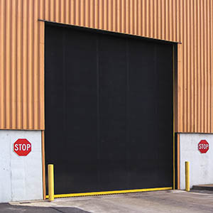
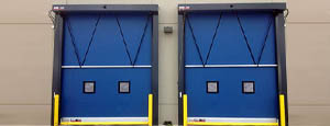
- Large Openings
Break-away functionality with rugged design seals oversized openings.
-
-
-
-
- Heavy Equipment
Withstands challenges of heavy equipment and fleet truck/car wash environments.
-
-
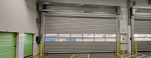
- Self-Storage
Fast opening speeds and reliable, durable construction keep facilities secure and protected.
-
-
- Industries
-
-
-
- Automotive Dealerships
Reduce energy costs, increase productivity and comfort and enhance customer perception.
-
-
- Cold Storage & Processing
Increase productivity and operational efficiency while reducing energy and maintenance costs.
-
-
- Parking
We offer solutions for Apartment / Condo & Loft, Standalone Parking Facilities and Office Buildings
-
-
-
-
- Food & Beverage
Doors specifically engineered for USDA/FDA and cGMP environments, and assured compliance for uncompromising performance.
-
-
- Mfg/Dist/Warehousing
A complete product line allows facilities to increase efficiency and safety and reduce maintenance and energy costs.
-
-
- Government
Ensure effective security and environmental controls are maintained for critical government operations.
-
-
-
-
- Transit
Keep operations running smoothly and efficient while reducing energy and maintenance costs.
-
-
- Pharma, Nutraceutical & Biotech
Doors that offer quick, secure access, environmental control and reliability for life science facilities.
-
-
- Support Resources
- Parts
- Contact Us
- Blog/News
- Why Rytec
- Sales Rep Locator
- Careers
- Dealers
- Architectural Resources







How to Choose the Right Electricity Controller in 2026?
Choosing the right Electricity Controller in 2026 requires more than comparing prices or counting available features. The correct device must match the load, operating environment, control method, and future maintenance plan. A controller may perform well in a clean laboratory but fail inside a hot, dusty electrical cabinet. That difference matters.
Frank D. Petruzella, author of Programmable Logic Controllers, describes a PLC as “a solid-state control system that has a user-programmable memory.” His statement remains useful because modern controllers still depend on reliable logic, accurate inputs, and predictable outputs. However, today’s selection process extends further. Buyers must examine network compatibility, cybersecurity protections, response time, energy monitoring, remote diagnostics, and integration with industrial automation platforms. Safety functions also deserve careful attention. A low-cost unit can become expensive when replacement parts are unavailable.
Look beyond the product brochure. Review wiring diagrams, communication protocols, enclosure ratings, and manufacturer support. Ask how the Electricity Controller behaves after a sensor fails. Ask whether technicians can troubleshoot it without specialized software. Small details matter. Terminal labels matter. Firmware updates matter.
Real projects often expose uncomfortable weaknesses. A controller can meet its listed specifications yet remain unsuitable for a noisy factory floor. I have seen selections fail because engineers focused on maximum capacity instead of actual operating conditions. That mistake is easy to repeat. The best choice balances performance, reliability, serviceability, and total ownership cost. It should also leave room for growth. No controller is perfect. Careful evaluation simply makes failure less likely.
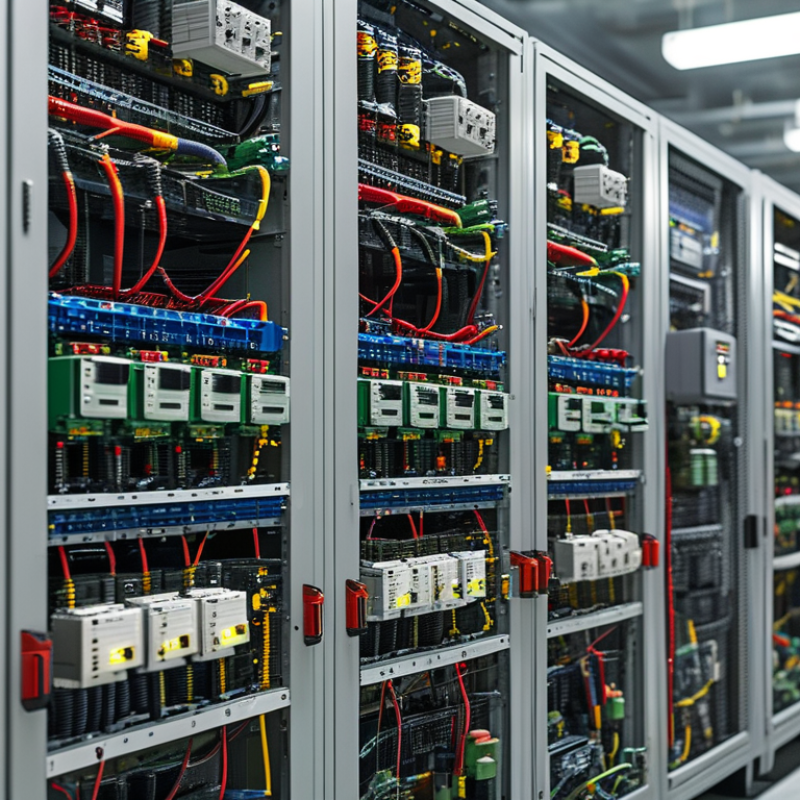
Table of Contents [Hide]
What an Electricity Controller Does and Why It Matters in 2026
An electricity controller manages how electrical power moves between a source, storage unit, and load. In a solar-battery system, it measures voltage and current several times each second. It can limit charging, disconnect an overloaded circuit, or direct power to a priority load. This prevents heat, unstable output, and premature battery wear. The controller is not merely a switch. It is the system’s decision point.
Its value becomes clearer in 2026, as homes and facilities combine solar panels, batteries, backup generators, heat pumps, and smart meters. A suitable controller coordinates these changing loads without wasting available energy. Look for accurate sensing, adjustable operating limits, fault logging, and communication options that match your installation. Check continuous current, peak current, operating temperature, enclosure rating, and battery chemistry compatibility. A unit rated for 40 amps may still fail if ventilation is poor or startup current is ignored. Small details matter.
Hands-on inspection should include terminal tightness, cable size, cooling space, and software update procedures. Ask how the controller behaves when sensors fail or the grid disappears. A safe system should enter a predictable state, not simply stop without warning. No controller is perfect. I would question impressive efficiency figures measured under ideal conditions. Real performance changes with dust, cold mornings, partial shading, and aging components. Choose a controller that remains understandable when conditions become inconvenient.