
- High-Performance Doors
-
- Applications
-
-
-
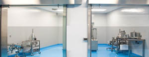
- Clean Room
Stainless steel or composite materials help maintain clean rooms.
-
-
- Coolers
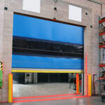
Quick opening speeds & tight seals for temperature control.
-
-
- Parking
Improve security & traffic flow and enhance architectural style.
-
-
- Hurricane Zone
Withstand winds up to 175 mph and comply with the Florida Building Code.
-
-
-
-
- USDA / FDA / cGMP
Increase productivity & address stringent USDA, FDA & cGMP requirements.
-
-
- Freezers
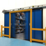
High-speed & perimeter seals minimize the air exchange between areas.
-
-
- Security
High speed & durability ensure secure access.
-
-
- Ventilation
Perforated or screen door panels allow improved air circulation.
-
-
-
-
- Fire Station Emergency Response
When time is of the essence, high speed and reliability are crucial.
-
-
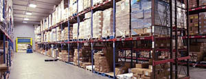
- Warehousing
Fast cycle times and secure seals keep environments separated.
-
-
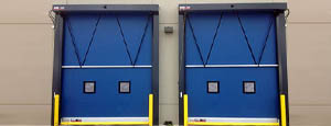
- Loading Dock
Rugged design & secure seal for oversized openings.
-
-
- Large Openings
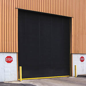
Break-away functionality with rugged design seals oversized openings.
-
-
-
-
- Heavy Equipment
Withstands challenges of heavy equipment and fleet truck/car wash environments.
-
-
- Self-Storage
Fast opening speeds and reliable, durable construction keep facilities secure and protected.
-
-
- Industries
-
-
-
- Automotive Dealerships
Reduce energy costs, increase productivity and comfort and enhance customer perception.
-
-
- Cold Storage & Processing
Increase productivity and operational efficiency while reducing energy and maintenance costs.
-
-
- Parking
We offer solutions for Apartment / Condo & Loft, Standalone Parking Facilities and Office Buildings
-
-
-
-
- Food & Beverage
Doors specifically engineered for USDA/FDA and cGMP environments, and assured compliance for uncompromising performance.
-
-
- Mfg/Dist/Warehousing
A complete product line allows facilities to increase efficiency and safety and reduce maintenance and energy costs.
-
-
- Government
Ensure effective security and environmental controls are maintained for critical government operations.
-
-
-
-
- Transit
Keep operations running smoothly and efficient while reducing energy and maintenance costs.
-
-
- Pharma, Nutraceutical & Biotech
Doors that offer quick, secure access, environmental control and reliability for life science facilities.
-
-
- Support Resources
- Parts
- Contact Us
- Blog/News
- Why Rytec
- Sales Rep Locator
- Careers
- Dealers
- Architectural Resources



















How to Choose Mould Components for Global Sourcing
Choosing Mould Components for global sourcing requires more than comparing catalogue prices. The right choice must fit the mould design, material, machine, production volume, and service expectations. A component that looks identical online may differ in steel grade, heat treatment, surface finish, or dimensional control. Those differences often appear later, when an ejector pin wears, a guide pillar binds, or a cooling channel leaks.
John Bozzelli, a respected injection-moulding consultant and founder of Scientific Molding, has repeatedly stressed this practical principle: “The process is the key, not the machine.” The same idea applies to sourcing Mould Components. A reliable supplier should explain how each part supports the process, not only provide a low quotation. Ask for material certificates, inspection records, tolerance data, and replacement lead times. Check whether the supplier understands your mould drawings and production conditions. Small details matter. A 0.02-millimetre mismatch can stop assembly. A poorly finished core pin can mark every moulded part.
Experience also teaches restraint. The cheapest component is not always economical. Yet the most expensive option may bring no measurable benefit. That is where careful comparison is necessary. Review samples, audit communication quality, and test critical parts before full production. I would not trust a supplier based on polished photos alone. Photos hide wear, measurement methods, and delivery problems. A sourcing plan should include approved alternatives, clear acceptance criteria, and realistic logistics. Global purchasing can reduce cost, but only when quality remains visible, measurable, and consistently controlled.
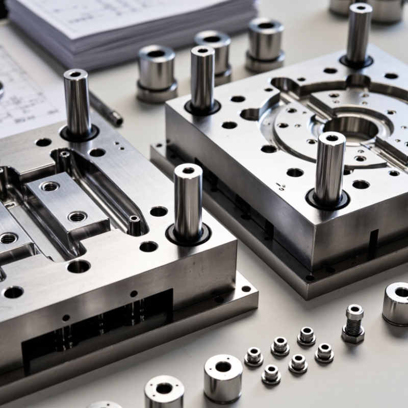
Table of Contents [Hide]
Define Mould Requirements: Part Size, Material, Tolerance and Cycle-Life Data
How to Choose Mould Components for Global Sourcing
Define mould requirements before comparing suppliers or component quotations. Record the part’s length, width, height, wall thickness, and projected area. Include the resin type, glass content, shrinkage range, and processing temperature. A small change in material can alter wear, cooling, and ejection performance. Do not guess.
Tolerance data needs practical detail. Identify critical dimensions, datum references, surface requirements, and acceptable flash limits. Separate cosmetic areas from functional areas. This prevents expensive precision where it adds no value. Check whether the tolerance suits the part’s function and the moulding process. A perfect drawing can still hide an unclear measurement method.
Cycle-life data should state the expected shot count, operating hours, maintenance intervals, and replacement limits. Describe the production rhythm, such as continuous three-shift operation or occasional batch use. For abrasive materials, specify expected wear on gates, slides, and ejector components. I have seen projects fail because cycle life was treated as a single number. It is not. Ask for inspection records, material certificates, hardness data, and trial results. Keep every revision controlled across time zones. Share a marked sample part when words are uncertain. A short video of the defect can also prevent a long argument. Resist choosing the lowest quotation before comparing assumptions, testing methods, and after-service responsibilities.