
- High-Performance Doors
-
- Applications
-
-
-
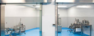
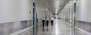
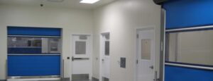
- Clean Room
Stainless steel or composite materials help maintain clean rooms.
-
-
- Coolers
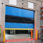
Quick opening speeds & tight seals for temperature control.
-
-
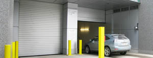
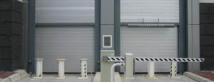
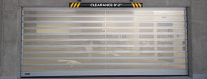
- Parking
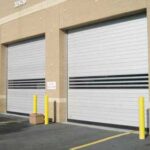
Improve security & traffic flow and enhance architectural style.
-
-
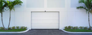
- Hurricane Zone
Withstand winds up to 175 mph and comply with the Florida Building Code.
-
-
-
-
- USDA / FDA / cGMP
Increase productivity & address stringent USDA, FDA & cGMP requirements.
-
-
- Freezers
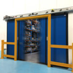
High-speed & perimeter seals minimize the air exchange between areas.
-
-
- Security
High speed & durability ensure secure access.
-
-
- Ventilation
Perforated or screen door panels allow improved air circulation.
-
-
-
-
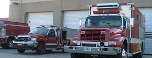
- Fire Station Emergency Response
When time is of the essence, high speed and reliability are crucial.
-
-
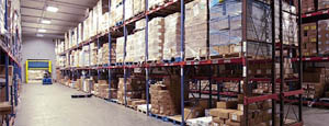
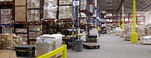
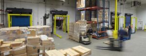
- Warehousing
Fast cycle times and secure seals keep environments separated.
-
-
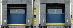
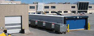
- Loading Dock
Rugged design & secure seal for oversized openings.
-
-
- Large Openings
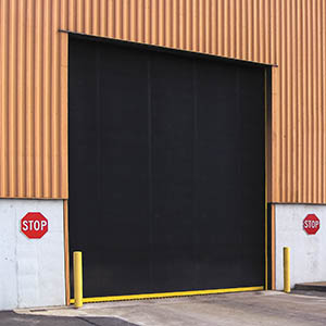
Break-away functionality with rugged design seals oversized openings.
-
-
-
-
- Heavy Equipment
Withstands challenges of heavy equipment and fleet truck/car wash environments.
-
-
- Self-Storage
Fast opening speeds and reliable, durable construction keep facilities secure and protected.
-
-
- Industries
-
-
-
- Automotive Dealerships
Reduce energy costs, increase productivity and comfort and enhance customer perception.
-
-
- Cold Storage & Processing
Increase productivity and operational efficiency while reducing energy and maintenance costs.
-
-
- Parking
We offer solutions for Apartment / Condo & Loft, Standalone Parking Facilities and Office Buildings
-
-
-
-
- Food & Beverage
Doors specifically engineered for USDA/FDA and cGMP environments, and assured compliance for uncompromising performance.
-
-
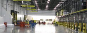
- Mfg/Dist/Warehousing
A complete product line allows facilities to increase efficiency and safety and reduce maintenance and energy costs.
-
-
- Government
Ensure effective security and environmental controls are maintained for critical government operations.
-
-
-
-
- Transit
Keep operations running smoothly and efficient while reducing energy and maintenance costs.
-
-
- Pharma, Nutraceutical & Biotech
Doors that offer quick, secure access, environmental control and reliability for life science facilities.
-
-
- Support Resources
- Parts
- Contact Us
- Blog/News
- Why Rytec
- Sales Rep Locator
- Careers
- Dealers
- Architectural Resources


What Is the Best Roof Sheet Roll Forming Machine in 2026?
Choosing the best Roof Sheet Roll Forming Machine in 2026 requires more than comparing speed and advertised capacity. A reliable machine must match the profile design, material thickness, production volume, and workshop conditions. Experienced buyers inspect the forming stations, shaft diameter, gearbox quality, cutting accuracy, and control system before signing a purchase order. They also examine finished sheets under real production pressure.
Metal roofing specialist Rob Haddock has often emphasized, “The roof is only as good as the details that protect it.” That principle applies to roll forming. A machine can produce attractive panels, yet poor alignment may create hidden stresses, uneven overlaps, or leaks during installation. Small errors matter. They become expensive on a long roof.
The strongest 2026 candidates should offer stable feeding, repeatable dimensions, quick profile changes, and accessible technical support. A practical example is a factory producing 0.50-millimeter galvanized steel sheets. It needs consistent rib height, clean cut edges, and minimal setup waste throughout an eight-hour shift. A faster line is not automatically better. Sometimes, a slower machine with stronger guides delivers fewer rejected panels.
There is no universal winner. That is worth admitting. Energy use, spare-part availability, operator training, and local service can change the decision completely. This guide compares those details carefully, while recognizing one uncomfortable truth: published specifications rarely reveal the full factory experience. Real performance appears after installation, maintenance, and repeated production cycles.
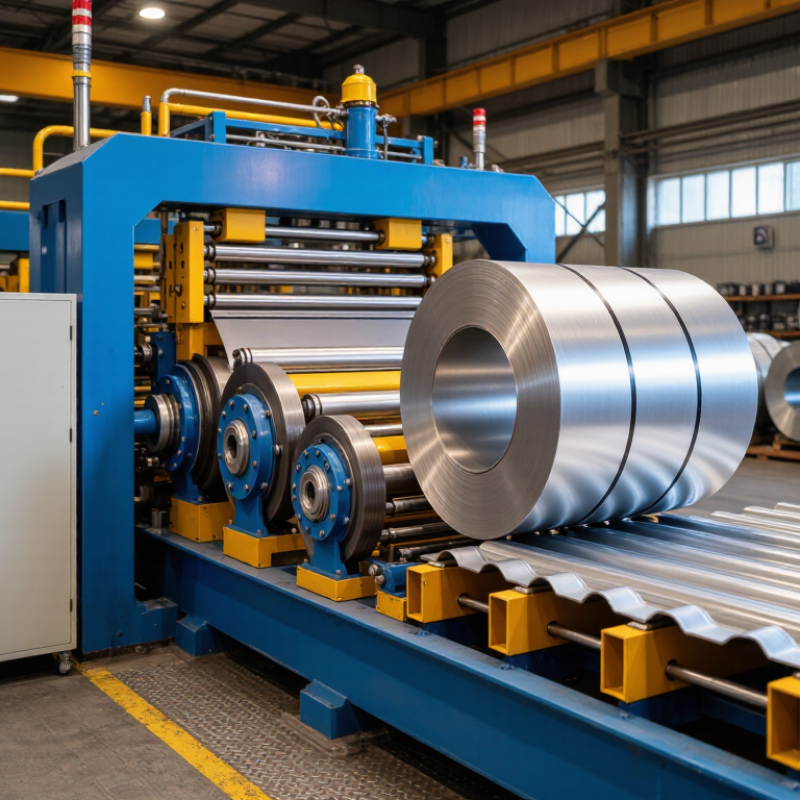
Table of Contents [Hide]
What Is a Roof Sheet Roll Forming Machine?
What Is the Best Roof Sheet Roll Forming Machine in 2026?
What Is a Roof Sheet Roll Forming Machine?
A roof sheet roll forming machine converts flat metal coils into continuous roofing panels. The process is steady and surprisingly precise. A typical line includes an uncoiler, guide rollers, forming stations, a cutting unit, and a control system. Each station bends the sheet gradually, rather than forcing one sharp fold.
On a production floor, galvanized steel or coated steel usually enters the machine as a coil. The rollers shape ribs, seams, or corrugations while maintaining the selected panel width. Hydraulic or servo-driven cutters then produce exact lengths without stopping the line. Even small alignment errors can create uneven edges, visible waves, or difficult installation.
The best machine in 2026 depends on the roof profile, material thickness, production volume, and available workspace. Look for adjustable guides, hardened rollers, clear controls, and accessible maintenance points. Accurate feeding matters more than impressive speed. A fast machine with poor calibration wastes material quickly. It also increases operator frustration.
Real performance needs testing. Ask for sample panels made from your intended steel grade and thickness. Check the finished profile with a measuring tool, not only by eye. Noise, vibration, and oil leakage deserve attention during inspection. Some specifications look excellent on paper, yet daily cleaning and roller adjustment may be inconvenient. That practical weakness should not be ignored.