
- High-Performance Doors
-
- Applications
-
-
-
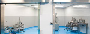
- Clean Room
Stainless steel or composite materials help maintain clean rooms.
-
-
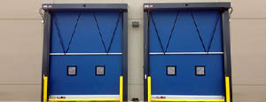
- Coolers
Quick opening speeds & tight seals for temperature control.
-
-
- Parking
Improve security & traffic flow and enhance architectural style.
-
-
- Hurricane Zone
Withstand winds up to 175 mph and comply with the Florida Building Code.
-
-
-
-
- USDA / FDA / cGMP
Increase productivity & address stringent USDA, FDA & cGMP requirements.
-
-
- Freezers
High-speed & perimeter seals minimize the air exchange between areas.
-
-
- Security
High speed & durability ensure secure access.
-
-
- Ventilation
Perforated or screen door panels allow improved air circulation.
-
-
-
-
- Fire Station Emergency Response
When time is of the essence, high speed and reliability are crucial.
-
-
- Warehousing
Fast cycle times and secure seals keep environments separated.
-
-
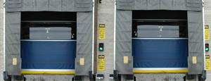
- Loading Dock
Rugged design & secure seal for oversized openings.
-
-
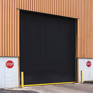
- Large Openings
Break-away functionality with rugged design seals oversized openings.
-
-
-
-
- Heavy Equipment
Withstands challenges of heavy equipment and fleet truck/car wash environments.
-
-
- Self-Storage
Fast opening speeds and reliable, durable construction keep facilities secure and protected.
-
-
- Industries
-
-
-
- Automotive Dealerships
Reduce energy costs, increase productivity and comfort and enhance customer perception.
-
-
- Cold Storage & Processing
Increase productivity and operational efficiency while reducing energy and maintenance costs.
-
-
- Parking
We offer solutions for Apartment / Condo & Loft, Standalone Parking Facilities and Office Buildings
-
-
-
-
- Food & Beverage
Doors specifically engineered for USDA/FDA and cGMP environments, and assured compliance for uncompromising performance.
-
-
- Mfg/Dist/Warehousing
A complete product line allows facilities to increase efficiency and safety and reduce maintenance and energy costs.
-
-
- Government
Ensure effective security and environmental controls are maintained for critical government operations.
-
-
-
-
- Transit
Keep operations running smoothly and efficient while reducing energy and maintenance costs.
-
-
- Pharma, Nutraceutical & Biotech
Doors that offer quick, secure access, environmental control and reliability for life science facilities.
-
-
- Support Resources
- Parts
- Contact Us
- Blog/News
- Why Rytec
- Sales Rep Locator
- Careers
- Dealers
- Architectural Resources






















7 Tips for Choosing a Flanged Type Globe Valve
Industrial facilities rarely choose a valve by appearance alone. A Flanged Type Globe Valve must control pressure, temperature, flow direction, and maintenance risk together. In steam, water, oil, and process piping, small selection errors can create noisy operation, leakage, or expensive shutdowns.
The International Energy Agency reported in World Energy Investment 2024 that global energy investment could reach about USD 3 trillion. This expanding infrastructure requires dependable flow-control equipment. The U.S. Department of Energy also identifies steam distribution losses as a major efficiency concern in industrial plants. That context makes correct valve sizing more than a purchasing detail. It affects energy use, reliability, and operational safety.
Details matter here. Check the valve’s pressure class against the piping system, not just the normal working pressure. Review body and trim materials for corrosion, erosion, and fluid temperature. Confirm the flow arrow before installation. A globe valve installed backward may produce unstable control and accelerated seat wear. Flange dimensions should match ASME B16.5 requirements, while face-to-face dimensions should follow the applicable ASME B16.10 specification. API 623 provides useful guidance for steel globe valves in petroleum and natural gas service.
Field experience also reveals an uncomfortable truth: supplier data sheets can be incomplete. A cheaper valve may hide poor packing design, weak testing records, or limited spare-parts support. These risks deserve questions. The following seven tips examine selection, certification, actuation, inspection, and lifecycle cost, while acknowledging that no checklist replaces a qualified engineering review. Mistakes happen. Good engineering catches them early.
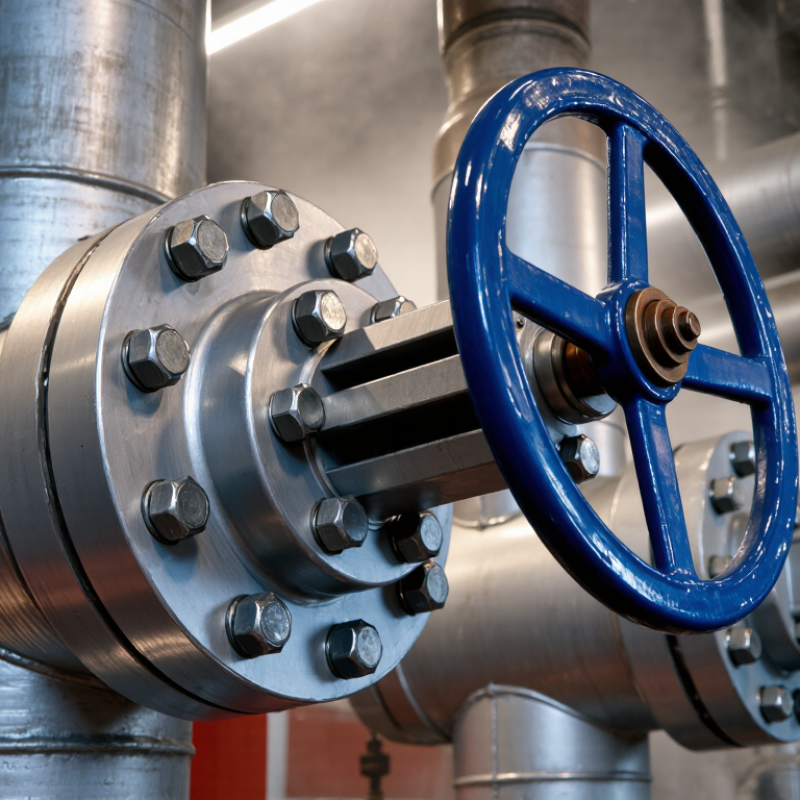
Table of Contents [Hide]
Understand Flanged Globe Valve Design and Operating Principles
7 Tips for Choosing a Flanged Type Globe Valve
Understand Flanged Globe Valve Design and Operating Principles
A flanged globe valve guides a movable disc against a fixed seat. The stem usually moves linearly through the bonnet. Its internal S-shaped passage improves throttling control, but it also creates noticeable pressure loss. That trade-off matters. The 2024 Fortune Business Insights report valued the global industrial valve market at about USD 78.96 billion in 2023. Growing demand does not make every valve suitable.
Check seven details carefully: medium compatibility, pressure-temperature rating, flow coefficient, seat material, body material, flange standard, and actuator force. ASME B16.34 helps verify pressure boundaries, while ASME B16.5 supports flange dimensional compatibility. A valve may fit visually yet fail during thermal cycling. Confirm the actual flange class, gasket type, bolt pattern, and installation temperature.
Use the valve where controlled flow is more important than minimum resistance. For steam, corrosive liquid, or high-cycle service, review trim hardness and packing performance. ISO 15848-1 provides a framework for fugitive-emission testing. The U.S. Department of Energy reports that optimized pumping systems can often reduce energy use by 30% to 50%; excessive valve pressure drop can undermine those savings. In field reviews, operators sometimes select oversized valves for comfort. That choice can weaken control and encourage unstable operation. I would still recheck the calculated Cv before ordering. Small errors become expensive.
7 Tips for Choosing a Flanged Type Globe Valve — Understand Flanged Globe Valve Design and Operating Principles
| Tip | Selection Focus | Flanged Globe Valve Design | Operating Principle | Key Data to Confirm | Main Benefit and Limitation |
|---|---|---|---|---|---|
| 1 | Define the Service Duty | A flanged globe valve uses a valve body with integral or bolted flanges for connection to a piping system. Its internal seat and disc are arranged to regulate or stop flow. | When the handwheel or actuator moves the stem, the disc travels toward or away from the seat. Partial disc movement changes the flow passage and allows throttling. |
| Benefit: Suitable for reliable isolation and flow regulation. Limitation: It is generally not the lowest-resistance choice for fully open flow. |
| 2 | Select the Correct Flow Direction | Globe valves commonly use a body passage that changes direction around the seat. Standard, angle, and Y-pattern bodies are available for different piping layouts and pressure-drop requirements. | Flow direction affects the pressure acting on the disc. Correct installation helps reduce unstable disc movement, seat damage, and excessive operating force. |
| Benefit: Correct direction can improve control stability and service life. Limitation: Incorrect orientation may increase torque and wear. |
| 3 | Match Pressure and Temperature Ratings | The pressure boundary includes the body, bonnet, stem, disc, seat, gasket, and bolting. Flange dimensions and pressure classes must be compatible with the piping system. | Internal pressure loads the body and closure components, while temperature changes affect material strength, gasket performance, and thermal expansion. |
| Benefit: Proper rating supports pressure-boundary integrity. Limitation: The allowable pressure may decrease as temperature rises. |
| 4 | Choose Materials for the Medium | Common body materials include carbon steel, stainless steel, and other engineered alloys. Internal trim materials may differ from the body to address wear, corrosion, or erosion. | The disc and seat repeatedly contact each other during operation. Material compatibility helps maintain sealing performance and limits corrosion, galling, and erosion. |
| Benefit: Correct material selection improves durability and leakage resistance. Limitation: Higher-alloy materials can increase cost and procurement time. |
| 5 | Check the Required Flow Capacity | Globe valves have a defined flow path and a movable disc. Their capacity is commonly evaluated using a flow coefficient such as Cv or an equivalent coefficient specified by the project. | Pressure loss results from changes in flow direction and restriction around the disc and seat. Throttling positions create greater resistance than the fully open position. |
| Benefit: Good sizing provides stable and controllable flow. Limitation: Oversizing can reduce control resolution; undersizing can cause excessive velocity and pressure loss. |
| 6 | Select the Appropriate Actuation Method | A globe valve may be operated by a handwheel, gearbox, pneumatic actuator, electric actuator, or hydraulic actuator. The stem may use a rising-stem arrangement that shows valve position visually. | The actuator applies linear force or thrust to move the stem and disc. The required force depends on differential pressure, seat load, packing friction, and operating temperature. |
| Benefit: Actuation can support remote control and process automation. Limitation: Actuators require correct sizing, commissioning, and maintenance. |
| 7 | Verify Flange, Sealing, and Maintenance Details | Flanged ends use bolts and a gasket to join the valve to matching pipe flanges. The bonnet, packing system, seat, and disc must also be accessible and suitable for the maintenance plan. | The flange gasket provides static sealing at the pipe connection, while stem packing limits leakage around the moving stem. The disc-to-seat interface provides internal shutoff. |
| Benefit: Correct connection details reduce installation and leakage problems. Limitation: Flanged valves need more space and more installation work than some compact end connections. |