
- High-Performance Doors
-
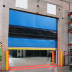
- Applications
-
-
-
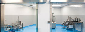
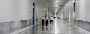
- Clean Room
Stainless steel or composite materials help maintain clean rooms.
-
-
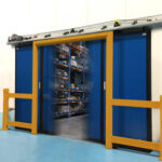
- Coolers
Quick opening speeds & tight seals for temperature control.
-
-
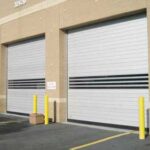
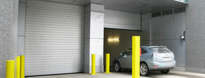
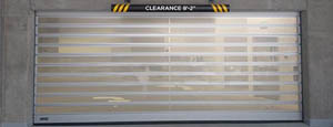
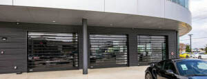
- Parking
Improve security & traffic flow and enhance architectural style.
-
-
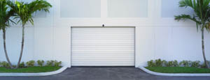
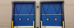
- Hurricane Zone
Withstand winds up to 175 mph and comply with the Florida Building Code.
-
-
-
-
- USDA / FDA / cGMP
Increase productivity & address stringent USDA, FDA & cGMP requirements.
-
-
- Freezers
High-speed & perimeter seals minimize the air exchange between areas.
-
-
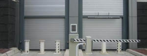
- Security
High speed & durability ensure secure access.
-
-
- Ventilation
Perforated or screen door panels allow improved air circulation.
-
-
-
-
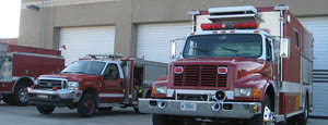
- Fire Station Emergency Response
When time is of the essence, high speed and reliability are crucial.
-
-
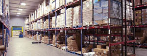
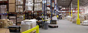
- Warehousing
Fast cycle times and secure seals keep environments separated.
-
-
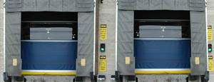
- Loading Dock
Rugged design & secure seal for oversized openings.
-
-
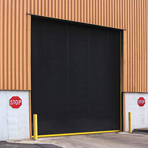
- Large Openings
Break-away functionality with rugged design seals oversized openings.
-
-
-
-
- Heavy Equipment
Withstands challenges of heavy equipment and fleet truck/car wash environments.
-
-
- Self-Storage
Fast opening speeds and reliable, durable construction keep facilities secure and protected.
-
-
- Industries
-
-
-
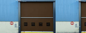
- Automotive Dealerships
Reduce energy costs, increase productivity and comfort and enhance customer perception.
-
-
- Cold Storage & Processing
Increase productivity and operational efficiency while reducing energy and maintenance costs.
-
-
- Parking
We offer solutions for Apartment / Condo & Loft, Standalone Parking Facilities and Office Buildings
-
-
-
-
- Food & Beverage
Doors specifically engineered for USDA/FDA and cGMP environments, and assured compliance for uncompromising performance.
-
-
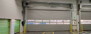
- Mfg/Dist/Warehousing
A complete product line allows facilities to increase efficiency and safety and reduce maintenance and energy costs.
-
-
- Government
Ensure effective security and environmental controls are maintained for critical government operations.
-
-
-
-
- Transit
Keep operations running smoothly and efficient while reducing energy and maintenance costs.
-
-
- Pharma, Nutraceutical & Biotech
Doors that offer quick, secure access, environmental control and reliability for life science facilities.
-
-
- Support Resources
- Parts
- Contact Us
- Blog/News
- Why Rytec
- Sales Rep Locator
- Careers
- Dealers
- Architectural Resources



7 Tips for Buying a Peripheral Driving Thickener?
Buying a Peripheral Driving Thickener is not simply a matter of choosing the largest tank. It is a process decision involving ore behavior, water recovery, torque, maintenance, and site conditions. USGS Mineral Commodity Summaries 2025 shows continuing global demand for mined materials, while water stewardship remains a major operational concern in the mining sector. Reports from the International Council on Mining and Metals also emphasize stronger water efficiency and responsible reuse.
A thickener may look calm from the walkway. Inside, clay, flocculant, and changing solids concentration can create unstable settling. That is why laboratory settling tests and pilot trials matter. Barry A. Wills, a recognized mineral-processing author, states: “The objective of thickening is to produce a thick pulp containing most of the solids and a clear liquid.” This principle remains practical when comparing underflow density, overflow clarity, and rake torque.
Seven buying considerations deserve close attention: feed characteristics, tank diameter, drive capacity, rake-lift protection, flocculant control, instrumentation, and after-sales support. Check real operating references. Ask for data from similar ore, not only ideal test conditions. A glossy datasheet is not enough. It can hide uncertainty.
The difficult part is prediction. Ore properties change. Seasonal water quality changes. My own recommendation is cautious: compare lifecycle performance, not purchase price alone. A cheaper Peripheral Driving Thickener may demand more maintenance, energy, or operator attention over time. That assumption can fail, so buyers should verify every critical claim through testing, documented references, and independent engineering review.
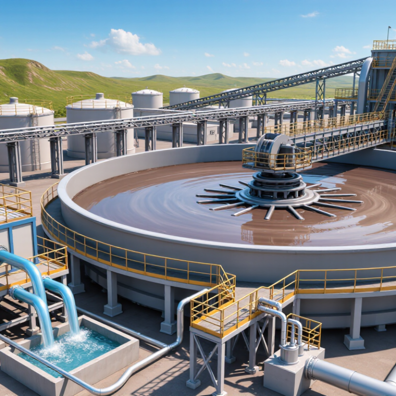
Table of Contents [Hide]
What Is a Peripheral Driving Thickener and How Does It Work?
A peripheral-drive thickener is a circular sedimentation unit used to concentrate suspended solids. Its drive mechanism sits near the tank rim. The motor turns a bridge and scraper assembly around the basin. Wastewater enters through a central feedwell, which reduces turbulence. Heavier particles settle slowly toward the bottom. Clearer liquid flows over the peripheral weir. Thickened sludge exits through a bottom outlet. The scraper moves settled solids toward that outlet.
When buying one, match the equipment to actual flow, solids loading, and tank diameter. A larger tank does not automatically provide better thickening. Ask for calculated torque, bridge load, and scraper speed. These figures reveal whether the drive can handle changing sludge conditions. Check the tank material, weld quality, and corrosion protection. Inspect the overload device and emergency stopping method. Small protection details can prevent expensive damage.
Reliable operation also depends on access. Review walkways, handrails, covers, and maintenance clearance before approval. Request drawings, operating data, and performance assumptions in writing. Compare expected underflow concentration with results from similar applications. Be cautious with optimistic numbers. Real plant conditions often differ from laboratory tests. I would also examine the control system, because simple alarms are easier to understand during a fault. Do not ignore winter conditions, grit, or uneven loading. These factors may expose weaknesses that appear invisible during a clean-water demonstration.