
- High-Performance Doors
-
- Applications
-
-
-
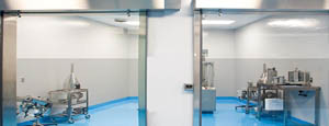
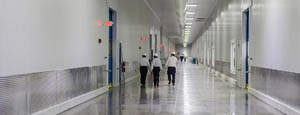
- Clean Room
Stainless steel or composite materials help maintain clean rooms.
-
-
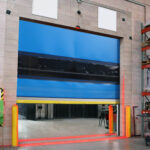
- Coolers
Quick opening speeds & tight seals for temperature control.
-
-
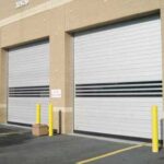
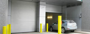
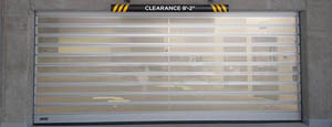
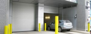
- Parking
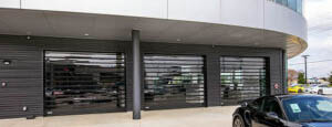
Improve security & traffic flow and enhance architectural style.
-
-
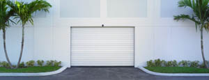
- Hurricane Zone
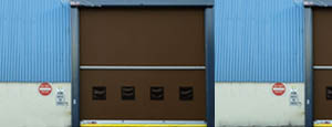
Withstand winds up to 175 mph and comply with the Florida Building Code.
-
-
-
-
- USDA / FDA / cGMP
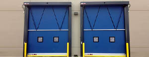
Increase productivity & address stringent USDA, FDA & cGMP requirements.
-
-
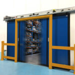
- Freezers
High-speed & perimeter seals minimize the air exchange between areas.
-
-
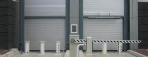
- Security
High speed & durability ensure secure access.
-
-
- Ventilation
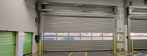
Perforated or screen door panels allow improved air circulation.
-
-
-
-
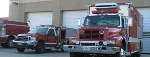
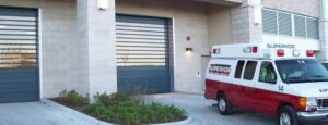
- Fire Station Emergency Response
When time is of the essence, high speed and reliability are crucial.
-
-
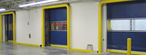
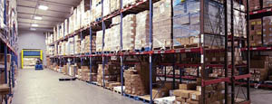
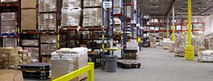
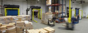
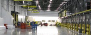
- Warehousing
Fast cycle times and secure seals keep environments separated.
-
-
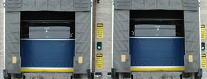
- Loading Dock
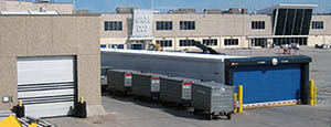
Rugged design & secure seal for oversized openings.
-
-
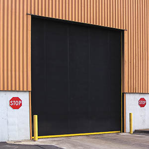
- Large Openings
Break-away functionality with rugged design seals oversized openings.
-
-
-
-
- Heavy Equipment
Withstands challenges of heavy equipment and fleet truck/car wash environments.
-
-
- Self-Storage
Fast opening speeds and reliable, durable construction keep facilities secure and protected.
-
-
- Industries
-
-
-
- Automotive Dealerships
Reduce energy costs, increase productivity and comfort and enhance customer perception.
-
-
- Cold Storage & Processing
Increase productivity and operational efficiency while reducing energy and maintenance costs.
-
-
- Parking
We offer solutions for Apartment / Condo & Loft, Standalone Parking Facilities and Office Buildings
-
-
-
-
- Food & Beverage
Doors specifically engineered for USDA/FDA and cGMP environments, and assured compliance for uncompromising performance.
-
-
- Mfg/Dist/Warehousing
A complete product line allows facilities to increase efficiency and safety and reduce maintenance and energy costs.
-
-
- Government
Ensure effective security and environmental controls are maintained for critical government operations.
-
-
-
-
- Transit
Keep operations running smoothly and efficient while reducing energy and maintenance costs.
-
-
- Pharma, Nutraceutical & Biotech
Doors that offer quick, secure access, environmental control and reliability for life science facilities.
-
-
- Support Resources
- Parts
- Contact Us
- Blog/News
- Why Rytec
- Sales Rep Locator
- Careers
- Dealers
- Architectural Resources

7 Best Lightning Arrestors for Global Buyers
Choosing the right Lightning Arrestor is not a simple matter of comparing prices, voltage ratings, or product photographs. Global buyers must examine discharge capacity, response time, grounding requirements, enclosure quality, and certification evidence. A device that performs well in a dry inland warehouse may struggle near a humid coastline. Installation conditions matter.
Dr. Martin A. Uman, a leading lightning researcher, stated, “There is no such thing as a lightning-proof structure.” His warning remains highly relevant. A Lightning Arrestor does not eliminate lightning risk. It creates a controlled path for surge energy and helps limit damage to electrical systems, equipment, and connected networks.
This guide reviews seven Lightning Arrestor options for international purchasing decisions. The selection considers practical performance, application range, maintenance needs, documentation, and value. It also recognizes an uncomfortable truth: product rankings are never universal. A model suited to a telecommunications tower may not fit a solar installation or industrial control cabinet.
Buyers should verify test reports, local system voltage, earthing design, and replacement support before ordering. Marketing language can sound convincing. It is not proof.
Some products appear impressive but provide limited technical detail. That deserves caution. The strongest choice is usually the one with transparent specifications, reliable testing, and a clear installation method. Regional standards may also differ, so professional review remains important. This list offers a practical starting point, not a substitute for site-specific engineering.
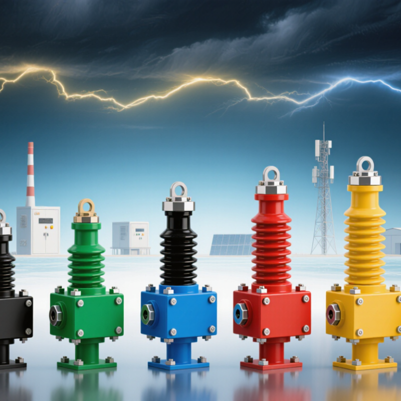
Table of Contents [Hide]
What Lightning Arrestors Are and How They Protect Electrical Systems
Lightning arrestors, often called surge protective devices, limit dangerous voltage spikes before they reach sensitive equipment. Lightning can travel through power, data, and grounding networks. The World Meteorological Organization reports that lightning occurs globally many times each second, creating a persistent risk for buildings, factories, and outdoor infrastructure.
An arrestor normally diverts excess current toward earth through a controlled discharge path. Its metal-oxide varistor changes behavior during a surge, then returns to a high-resistance state. IEC 61643-11 defines key performance requirements for low-voltage surge protective devices. Buyers should compare maximum continuous operating voltage, nominal discharge current, maximum discharge current, and voltage protection level. A lower protection level usually offers stronger equipment protection.
Installation matters greatly. A well-rated device can fail when grounding conductors are too long, loose, or poorly bonded. The National Electrical Code recommends short, direct connections, while IEC guidance supports coordinated Type 1, Type 2, and Type 3 protection. Type 1 devices handle high-energy incoming surges. Type 2 units protect distribution boards. Type 3 devices serve sensitive loads near the outlet.
Look beyond impressive numbers. A 2024 Allianz Risk Barometer survey identifies cyber incidents and business interruption among major global business concerns, but physical surge damage can trigger both. In field inspections, overlooked signal lines often become the weak point. No arrestor is magic. Local lightning density, system voltage, earthing quality, and maintenance records should shape the final choice.